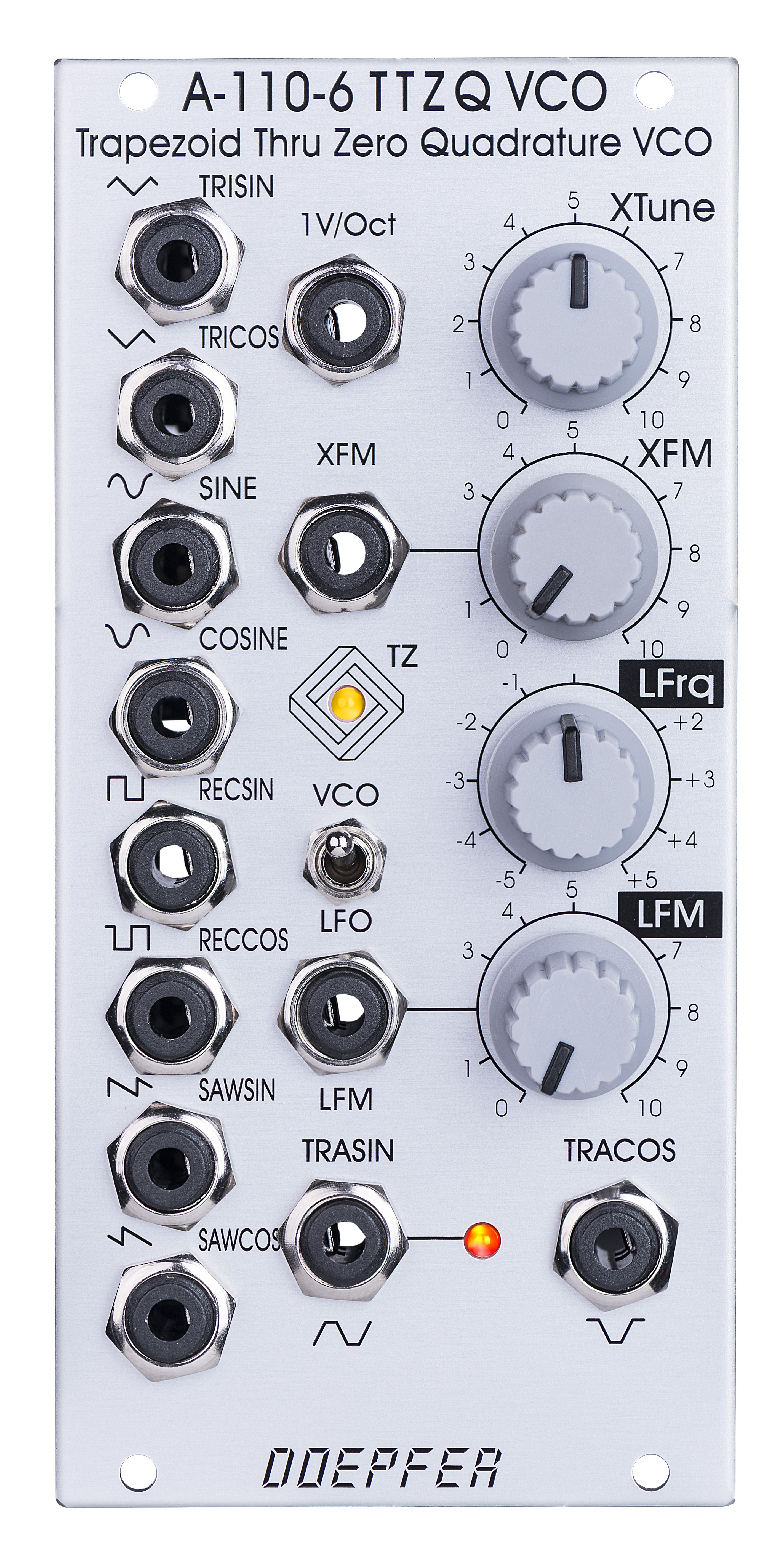
A-110-6 Trapezoid Thru Zero Quadrature VCO
|
click to enlarge |
|
|
A-110-6 Waveforms
|
A-110-6 beruht auf einem völlig anderen Design als gängige VCOs und verwendet ein sog. Quadratur-Trapezoid als Grundwellenform (normalerweise werden bei VCOs Sägezahn oder Dreieck als Grundwellenform verwendet). Zusätzlich zu dieser speziellen Wellenform-Kombination bietet das Modul auch lineare Thru Zero Frequenzmodulation und sog. Quadratur-Ausgänge für alle Wellenformen (d.h. jeweils zwei um 90 Grad phasenverschobene Signale). Die beiden Grundwellenformen werden mit Trapezoid-Sinus (TRASIN) und Trapezoid-Cosinus (TRACOS) bezeichnet. Die anderen Standard-Wellenformen (Dreieck, Sinus, Sägezahn und Rechteck) werden aus diesen beiden Kurvenformen durch Waveshaper abgeleitet. Das Modul basiert auf einer Idee von Donald Tillman aus dem Jahr 2003, wurde aber von uns komplett überarbeitet und an den Einsatz moderner Bauteile angepasst (keine OTAs/CA3280).
Das
Modul verfügt über zwei Steuer-Einheiten: eine lineare und eine
exponentielle:
Die exponentielle Sektion besteht aus dem Regler XTune, dem
1V/Oktave-Steuereingang und dem exponentiellen FM-Eingang XFM mit zugehörigem
Abschwächer.
Die lineare Sektion besteht aus dem Regler LFrq und dem linearen
FM-Eingang LFM mit zugehörigem Abschwächer.
Die Tonhöhe aller Ausgänge ist bestimmt durch die Steuerspannungen
beider Sektionen. Die lineare Sektion steuert die Frequenz über eine
linearen Kennlinie.
Steht
der Regler LFrq auf Rechtsanschlag, so arbeitet das Modul wie ein
"normaler" VCO und die Tonhöhe wird von der exponentiellen
Einheit mit dem Regler Xtune, dem exponentiellen FM-Eingang XFM und dem
1V/Oktave-Steuereingang in der üblichen Weise eines VCOs gesteuert.
Wird der Regler LFrq vom Rechtsanschlag beginnend gegen den Uhrzeigersinn
gedreht, so ändert sich die Frequenz mit einer linearen Kennlinie und
kommt etwa in Mittelstellung (nahezu) zum Stillstand. Wird
der Regler weiter gegen den Uhrzeigersinn gedreht, so beginnt die
Schwingung von Neuem, jedoch in umgekehrter Richtung. Ist
der Linksanschlag des Reglers LFrq erreicht, so arbeitet das Modul wieder
als "normaler" VCO.
Das Anlegen eines Modulationssignals (z.B. ein anderer VCO) an den
linearen FM-Eingang LFM erzeugt jedoch weitaus interessante Klänge als
nur die manuelle Betätigung des LFrq-Reglers. Hiermit erhält man die
typischen Klänge, die nur mit Hilfe der linearen Frequenzmodulation (und
insbesondere der Thru-Zero-Modulation) möglich sind. Die Kombination von
Trapezoid-Kurvenformen in Quadratur zusammen mit der linearen
Thru-Zero-Modulation ermöglicht Klangspektren, die von keinem anderen VCO
erzeugt werden können.
Das Modul stellt gleichzeitig folgende Kurvenformen zur Verfügung, wobei
jede Kurvenform als sogenanntes Quadratur-Paar (d.h. auch um 90 Grad
verschoben) vorhanden ist:
-
Trapez (TRASIN + TRACOS)
-
Dreieck (TRISIN + TRICOS)
-
Sinus (SIN + COS)
-
Rechteck (RECSIN + RECCOS)
-
Sägezahn (SAWSIN + SAWCOS)
Mit
Hilfe eines Kippschalters kann das Modul auch in den LFO-Modus gebracht
werden. Im LFO-Modus sind die Frequenzen um den Faktor 100 kleiner als im
VCO-Modus.
Eine
zweifarbige LED zeigt die Polarität der linearen Kontrolleinheit an. Eine
zweite zweifarbige LED zeigt das Signal TRASIN an, was speziell im
LFO-Modus sinnvoll ist.
Technische Hinweise:
-
Der LFM CV-Eingang ist gleichspannungsgekoppelt (DC coupled). Falls der Eingang für lineare FM im Audiobereich genutzt wird und das Eingangssignal eine Gleichspannungskomponente besitzt (DC offset), so resultiert das in einer Tonhöhenverschiebung, die von der Höhe des Gleichspannungs-Offsets abhängt. Insbesondere wenn ein VCA verwendet wird, um den Pegel des Modulationssignals dynamisch zu ändern, kann es zu Tonhöhenverschiebungen kommen, wenn das Ausgangssignal des VCAs eine Gleichspannungskomponente besitzt. Diese wird durch den sog. Steuerspannungs-Durchgriff (control voltage feedthrough) verursacht, der in der Regel von der dem VCA zugeführten Steuerspannung abhängt. In diesem Fall würde sich also die Tonhöhe des A-110-6 bei Änderung der VCA-Steuerspannung ändern. Es sollte für diese Anwendung daher ein VCA mit einem möglichst geringen Steuerspannungs-Durchgriff verwendet werden (VCAs ganz ohne CV-Feedthrough sind kaum zu finden). Eine andere Möglichkeit besteht darin, das Signal wechselspannungsmäßig am LFM-Eingang einzukoppeln (z.B. durch Einfügen eines Kondensators in die Signalleitung)
-
Die Steuerspannung, die an der Buchse 1V/Oct anliegt, wird zu der vom Bus kommenden Steuerspannung addiert (unterbrechbar durch Entfernen der Steckbrücke JP3 / beschriftet mit "CV BUS" auf der Leiterplatte). Wird ein Kabel in die Buchse 1V/Oct gesteckt, so wird die vom Bus kommenden Steuerspannung nicht unterbrochen (d.h. die Buchse 1V/Oct ist nicht auf die Bus CV normalisiert) ! Dies ermöglicht beispielsweise die Transponierung einer CV-Sequenz, die an 1V/Oct anliegt, mit der Bus CV, die z.B. von einem Midi-CV-Interface kommt.
-
Das Dokument A110_6_trimming_potentiometers.pdf zeigt die Positionen und Funktionen der Trimmpotentiometer und Steckbrücken. Wir weisen vorsorglich darauf hin, dass falsche Justierungen durch das Verändern der Trimmpotentiometer-Einstellungen seitens des Kunden nicht von der Garantie abgedeckt sind. In diesem Fall müssen wir ggf. die Arbeitszeit für die Neujustierung des Moduls in Rechnung stellen !
A-110-6 is a Trapezoid Thru
Zero Quadrature VCO. The module is based on an idea by Donald Tillman from
2003 but has been revised for the use of modern electronic circuits (no
OTAs/CA3280). Because of it's unique trapezoid core it's totally
different compared to other VCOs. But the trapezoid core is not the only
specialty: it is also a quadrature VCO and features linear thru zero
frequency modulation.
The term "quadrature" means in this connection that the
oscillator outputs two trapezoid waves with 90 degrees phase shift. The
same as sine and cosine of a standard quadrature oscillator like the A-110-4
or A-143-9. These
waveforms are called TRASIN (trapezoid sine) and TRACOS (trapezoid
cosine).
The term
"Thru-Zero" means that even "negative" frequencies are
generated. But this a bit a misleading term as negative frequencies do not
really exist. "Negative" means in this connection simply that
the TRASIN/TRACOS waves will stop when the linear control voltage reaches 0V
and continue with the opposite directions as the linear control voltage
becomes negative and vice versa.
The
module has two control sections: linear and a exponential. The exponential
section consists of the XTune control, the 1V/Oct input and the XFM input
with the corresponding attenuator XFM. The exponential control voltage is
the sum of these three voltages. The linear section consists of the LFrq
control and the LFM input with the corresponding attenuator LFM. The
linear control voltage is the sum of these two voltages. A dual color LED
is used to display the polarity of the linear control voltage. The pitch of all outputs
is determined by the control voltages of both sections. The
linear section is used to control the pitch in a linear manner. When the LFrq control
(LFrq means Linear Frequency Control) is fully CW the module works like
a normal VCO and the LED lights red. The pitch is then controlled by the exponential
section with the manual Tune control XTune and the exponential frequency control
inputs 1V/Oct and XFM. 1V/Oct is used to control the pitch by a 1V/Oct CV
source (e.g. sequencer or Midi/USB-to-CV interface). XFM is used to apply
an exponential frequency modulation with adjustable depth (e.g. from an
LFO or another VCO). As the LFrq control is turned counterclockwise
starting from the fully CW position the frequency is lowered in a linear
manner until the TRASIN/TRACOS waves (nearly) stop at the center position of
LFrq
(provided that no LFM signal is present). As the LFrq control is moved
from the center towards the CCW position the waves start again but into
reverse direction and the LED turns yellow. When the fully CCW position of
LFrq is reached the module works again like a normal VCO. But
much more exciting is the usage of the LFM input to modify the linear
control voltage by an external control voltage (typically another VCO).
Linear modulation by another oscillator using the thru zero feature in
combination with the trapezoid waveforms generates audio spectra than cannot be obtained from any
other oscillator without
the thru zero function. The reason is that a "normal" VCO will
simply stop as the linear control voltage becomes zero or negative. But a
thru zero VCO will start again with "negative" frequencies as
the the linear control voltage becomes negative.
Other waveforms like triangle, sawtooth, rectangle and sine can be
obtained from the TRASIN/TRACOS signals (triangle e.g. simply
by subtracting TRISIN and TRICOS, SAWSIN and SAWCOS by switching the other
waveforms). All five waveforms are available as
quadrature pairs (i.e. with 90 degrees phase shift):
-
Trapezoid (TRASIN + TRACOS)
-
Triangle (TRISIN + TRICOS)
-
Sinus (SIN + COS)
-
Rectangle (RECSIN + RECCOS)
-
Sawtooth (SAWSIN + SAWCOS)
By means of a toggle switch the frequency range can be selected between VCO (audio range) and LFO. In LFO range the frequencies are about 1/100 compared to VCO mode.
A
dual-color LED display the polarity of the linear control section.
Another dual-color LED shows the signal TRASIN which is helpful in LFO
mode.
Technical notes:
-
The LFM CV input is DC coupled. If the input is used for linear FM in audio range and the signal applied to this input has a DC offset it will cause a small pitch shift that depends upon the value of the DC voltage. Especially when a VCA is used to change dynamically the level of the modulation signal this may generate a pitch shift caused by the control voltage feedthrough of the VCA. The control voltage feedthrough adds a DC voltage at the output which depends upon the control voltage of the VCA. For this application VCAs with a very low CV feedthough should be used or the signal output of the VCA should be AC coupled to the LFM input of the A-110-6 (e.g. by inserting a capacitor)
-
The control voltage applied to the socket 1V/Oct is added to the control voltage coming from the bus (interruptible by removing the jumper JP3 / labelled "CV BUS"). Connecting a cable to the socket 1V/Oct does not interrupt the bus CV connection ! I.e. the 1V/Oct socket is not normalled to the bus CV. This allows e.g. transposing sequence CV (applied to the socket 1V/Oct) by the bus CV (e.g. connected to the CV output of a Midi-to-CV interface).
-
The document A110_6_trimming_potentiometers.pdf explains the functions of the trimming potentiometers. The document is planned only for experienced users ! Please do not change the settings of the trimming potentiometers unless you are sure that you want to change certain settings. Modules which are returned with (mis-)adjusted trimming potentiometers cannot be treated as case of warranty !
Tiefe/Depth: 55 mm (gemessen ab der Rückseite der Frontplatte / measured from the rear side of the front panel)
Strombedarf/Current: +80mA (+12V) / -70mA (-12V)
The price in US$ depends upon the exchange rate between Euro and US$ at the payment day.