A-134-2 Dual Voltage Controlled Crossfader
|
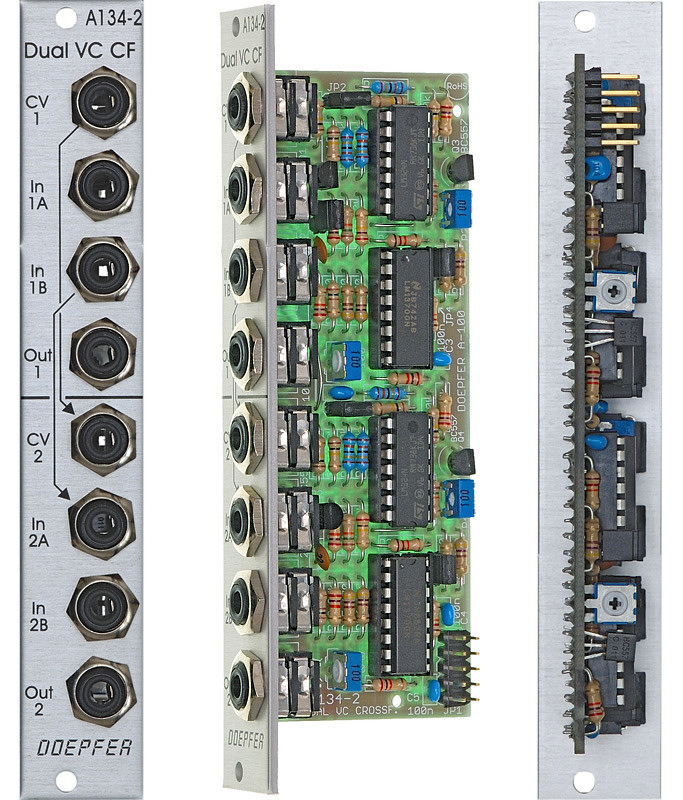
Module A-134-2 contains two identical voltage controlled crossfader units.
Each unit has two voltage controlled amplifiers (VCAs) with opposite control behaviour available. The outputs of the two VCAs are mixed together to obtain a common output. The behaviour of the control voltage inputs can be chosen with an internal jumper:
Symmetrical mode: If the corresponding jumper is not set both VCAs of the crossfader have the same 50% amplification with zero CV. If the applied CV becomes positive the amplification of VCA1 decreases and those of VCA2 increases in the same way. A negative CV has the opposite result. The CV voltage range to obtain the maximum/minimum positions of the crossfader is about -2.5....+2.5V. This mode is useful for bidirectional (i.e. positive and negative) control voltages, for example LFO or joy stick (adjusted to 0V CV in center position).
Asymmetrical mode: If the corresponding jumper is set VCA2 is fully closed and VCA1 has full 100% amplification with zero CV. If the applied CV becomes positive the amplification of VCA1 decreases and those of VCA2 increases in the same way. The CV voltage range to obtain the maximum/minimum positions of the crossfader is about 0....+5V. A negative CV has no function in this mode. This mode is useful for unidirectional (i.e. only positive) control voltages, for example ADSR, ribbon controller or Theremin control voltage.
The CV input of the upper unit (CV1) is normalled to the CV input of the lower unit (CV2). I.e. if no plug is inserted to CV2 the CV input of the upper unit (CV1) also controls the lower unit.
The second signal input of the upper unit (In1B) is normalled to the first signal input of the lower unit (In2A). I.e. if no plug is inserted into In2A the signal In1B is used as the first signal input of the second unit.
As the inputs and outputs are DC coupled the module can be used for both audio and control voltage signal processing.
The module can be modified to have only one common output available, i.e. output 1 and output 2 are mixed together and appear at the Out 2 socket. With this modification the module can be used in combination with the Joy Stick module A-174 as a two-dimensional crossfader, i.e. four signals are mixed to one output with the joy stick position defining the relation between the signals. In this application Out 1 has no function. Both units of the A-134-2 have to be set to symmetrical mode:
- Joystick in center position (CVX = 0V, CVY = 0V): In1A = 50%, In1B = 50%, In2A = 50%, In2B = 50%, i.e. all four signals have nearly the same level
- Joystick in upper position (CVY ~ +3.5V, CVX = 0V): In1A = 100%, In1B = 0%, In2A = 50%, In2B = 50%
- Joystick in lower position (CVY ~ -3.5V, CVX = 0V): In1A = 0%, In1B = 100%, In2A = 50%, In2B = 50%
- Joystick in right position (CVY = 0V, CVX ~ +3.5V): In1A = 50%, In1B = 50%, In2A = 100%, In2B = 0%
- Joystick in left position (CVY = 0V, CVX ~ -3.5V): In1A = 50%, In1B = 50%, In2A = 0%, In2B = 100%
Applications:
- Using the CV X and CV Y outputs of the joy stick module A-174 to crossfade between different audio or control voltage signals:
- voltage controlled crossfading ("morphing") between audio signals (e.g. two VCO waveforms or VCO and noise or two VCF outputs)
- voltage controlled crossfading between different modulation voltages (e.g. two different LFO waveforms of the same LFO, two different LFOs or LFO and ADSR)
Meaning of the jumpers:
- JP2: offset upper unit (when installed offset = 0V, when not installed offset = +2.5V)
- JP3: offset lower unit (when installed offset = 0V, when not installed offset = +2.5V)
- Individual outputs for upper/lower unit: JP4, JP5 and JP6 installed
- common output Out 2 for both units: JP4 and JP5 installed, JP6 removed and the pins of JP4 and JP5 have to be connected (as jumpers are installed to JP4 and JP5 it does not matter which of the pins of JP4 and JP5 are connected). In this case the socket Out 1 has no function and Out 2 is the sum output for both units!
A-134-2 schema
Technical note: Actually the module does amplify the signal "In 1" by about 1.5 (or about 4 dB) instead of 1 (0 dB) when the control voltage is 0V in the asymmetrical mode. As well signal "In 2" is amplified by 1.5 when the control voltage is about +5V. In other words the amplification of the VCAs is in the 0...1.5 range rather than the usual 0...1 for other VCAs. If the range 0...1 is necessary attenuators can be used at the inputs (e.g. A-183-1).
Tiefe/Depth: 45 mm (gemessen ab der Rückseite der Frontplatte / measured from the rear side of the front panel)
Strombedarf/Current: +20mA (+12V) / -10mA (-12V)
The price in US$ depends upon the exchange rate between Euro and US$ at the payment day.