A-154 Sequencer Controller
|
|
|
|
|
|
|
|
Vintage Edition |
|
-
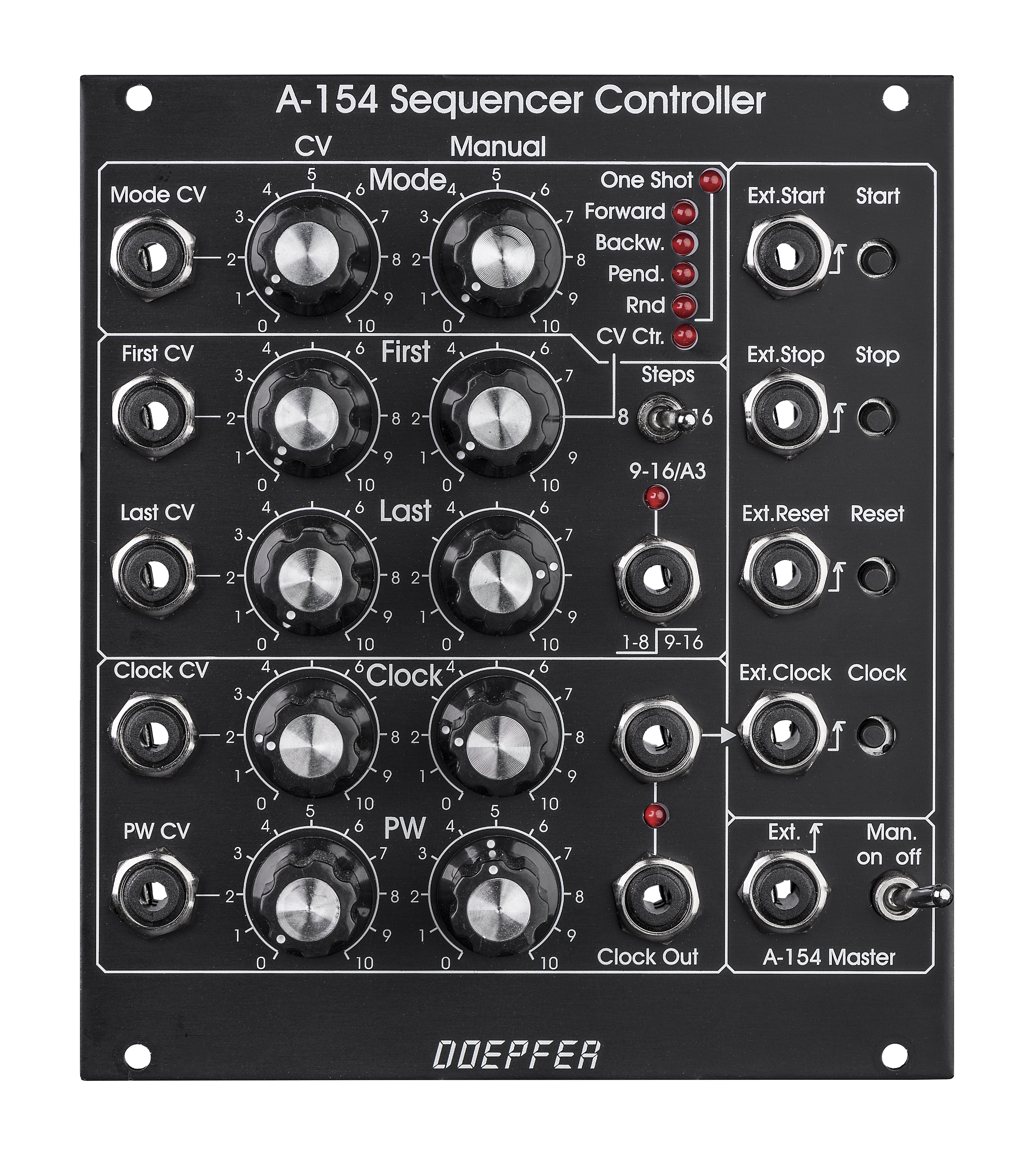
Bedienungselemente:
Manual Mode
Mode CV (Abschwächer)
Mode Anzeige (5 LEDs)
One Shot Anzeige (1 LED)
Manual First Step (= Addressed Step)
First Step CV (Abschwächer)
Manual Last Step
Last Step CV (Abschwächer)
Manual Clock
Clock CV (Abschwächer)
Manual PW
PW CV (Abschwächer)
Clock Anzeige (LED)
8/16 Step (Schalter)
Start,Stop,Step Reset (Taster)
A-154 Master (Schalter)
- Ein/Ausgänge:
Mode CV
First Step CV (= Addressed Step CV)
Last Step CV
Clock CV
PW CV
9-16/A3 Out
Clock Out (2x)
Start, Stop, Reset, Step (Eingangsbuchsen)
A-154 Master (Gate-Eingangsbuchse)
Der A-154 ist ein Erweiterungsmodul für den A-155 Analog/Trigger Sequenzer und bietet eine Reihe neuer Funktionen, die in der einfachen Steuerlogik des A-155 nicht vorhanden sind. Mit dem A-154 können einer oder zwei A-155 parallel gesteuert werden. Der A-154 ersetzt die bisherige Steuereinheit des A-155 (d.h. der Bereich der A-155-Frontplatte mit Start / Stop / Step / Reset-Tastern und -Eingängen). Hier die wichtigsten Neuerungen, die der A-154 gegenüber dem A-155 bietet:
-
Verschiedene Betriebsarten: vorwärts, rückwärts, pendeln, zufällig und spannungsgesteuerte Adressierung - jeweils im Loop-Betrieb (endlos) oder im One-Shot-Betrieb (nur einmaliger Durchlauf der Sequenz)
-
LED-Anzeige der gewählten Betriebsart (5 + 1 für One-Shot-Anzeige)
-
Manuelle und spannungsgesteuerte Wahl der Betriebsart. Der externe Steuereingang ist mit einem Abschwächer ausgestattet, um die Stärke der Beeinflussung der Betriebsart durch die externe Steuerspannung einstellen zu können. Die momentan gewählte Betriebsart wird durch 5 LEDs angezeigt. Eine weitere LED zeigt an, ob der One-Shot-Modus aktiv ist.
-
Manuelle und spannungsgesteuerte Wahl von erstem (First Step) und letztem Schritt (Last Step) der Sequenz, Bereich 1...8 (im 8-Step-Modus) bzw. 1...16 (im 16-Step-Modus)
-
In der Betriebsart "CV Step Address" (spannungsgesteuerte Step-Adressierung) wird die aktive Sequenzer-Stufe durch die "First Step"-Einstellung bestimmt (in dieser Betriebsart ist First/Last Step nicht aktiv). Somit sind manuelle und durch eine externe Spannung gesteuerte Adressierung möglich und die aktive Stufe kann von Hand gewählt und dann durch eine externe Steuerspannung (LFO, Random, S&H, Theremin, Joy Stick) moduliert werden.
-
Interner spannungsgesteuerter Clock-Generator mit manueller Einstellung des Tempos und CV-Eingang mit Abschwächer. Das Clock-Signal wird mit einer LED angezeigt und als Clock-Signal für den Sequencer verwendet, sofern kein externes Clock-Signal in die Clock In-Buchse gesteckt wird ("normalisierte" Buchse). Wird der CV-Eingang der Clock-Einheit mit einem der Analogausgänge des A-155 verbunden, kann die Zeitdauer für jede Stufe getrennt eingestellt werden. Auch Sprünge (jumps / skipping) ist möglich, da die Clock-Einheit oberhalb einer bestimmten Steuerspannung einen kurzen Impuls erzeugt, der sofort zur nächsten Stufe weiterschaltet. Für diese "Skipping-Funktion" kann beispielsweise die Gate-Reihe des A-155 verwendet werden.
-
Manuelle Einstellung der Pulsbreite (PW) des Clock-Generators und CV-Eingang mit Abschwächer. Diese Funktion ermöglicht unterschiedlich lange Gate-Zeiten für jede Stufe (z.B. gesteuert von einem Analogausgang des A-155 oder "automatisch" mit Hilfe von LFO/Random/S&H).
-
8/16 Stufen-Modus: Mit einem Kippschalter kann zwischen 8 und 16 Sequenzerstufen gewählt werden. Für den "16 Step"-Modus sind zwei A-155 und ein oder mehrere spannungsgesteuerte Schalter erforderlich (z.B. A-150-1 oder A-150-8). Der bzw. die spannungsgesteuerten Schalter werden vom Ausgang "A3" des A-154 gesteuert. Dieser Ausgang liegt auf "low", solange einer der Stufen 1...8 aktiv ist und geht auf "high" im Bereich 9...16. Über die spannungsgesteuerten Schalter erfolgt die Umschaltung zwischen den CV/Trigger/Gate-Ausgängen des ersten (1...8) und zweiten A-155 (9...16). In der Anleitung ist der entsprechende Patch skizziert.
-
Manuelle und spannungsgesteuerte Umschaltung zwischen "alter" Controller-Einheit des A-155 und Steuerung der A-155 über den A-154 (A-154 Master an/aus-Funktion)
Anmerkung: Die One-Shot-Betriebsarten erlauben die Verwendung des A-155 zusammen mit dem A-154 auch als komplexer Hüllkurvengenerator. Das Gate- bzw. Trigger-Signal wird dabei dem Start-Eingang des A-154 zugeführt. Eine Analogreihe des A-155 legt dabei die Pegelstufen fest, die zweite Analogreihe kann dazu verwendet werden, um die Zeitdauer für jede der Stufen variabel zu gestalten. Die Gate-Reihe kann z.B. dazu verwendet werden zwischen weichen (Gleit-Funktion des A-155 angeschaltet) und harten Stufen (Gleit-Funktion des A-155 abgeschaltet) zu wählen. Bei der One-Shot-Betriebsarten von Random läuft die Sequenz so lange, bis zufällig die letzte Stufe angewählt wird. Danach stoppt die Sequenz. Die Kombination von One-Shot und CV-Adressierung ist nicht vorgesehen, das diese Kombination unserer Meinung nach wenig Sinn macht.
Einbau des A-154: Die Funktionen der Start/Stop/Step/Reset-Taster und -Eingänge sind die gleichen wie beim A-155. Der A-154 wird verwendet um die "alte" Steuereinheit eines oder mehrerer A-155 zu ersetzen. Wird ein A-154 zur Steuerung eines A-155 verwendet, so wird über die A-154 Master-Funktion (Schalter und Gate-Steuereingang) am A-154 gewählt, ob die "alte" Steuereinheit des A-155 benutzt wird oder diese ausser Funktion gesetzt und stattdessen die Steuerung vom A-154 übernommen wird. Die 10-polige Steckverbindung vom A-155 muss hierzu beim Einbau des A-154 auf den A-154 umgesteckt werden und die neue Steuerung auf den A-155 aufgesteckt werden. Der A-154 muss daher möglichst direkt rechts neben dem A-155 angeordnet werden. Bei zwei A-155 müssen die beiden A-155 untereinander und der A-154 neben dem oberen oder unteren A-155 montiert werden. Werden zwei A-155 eingesetzt, so können diese parallel (8 Stufen) oder seriell (16 Stufen) betrieben werden. Der 8/16 Schalter am A-154 legt dabei fest, ob der "8 Step Mode" (zwei A-155 parallel) oder der "16 Step Mode" (zwei A-155 seriell) gewählt wird. Beide Betriebsarten funktionieren auch mit spannungsgesteuerter Adressierung. Im "8 Step Modus" werden nur die Stufen 1...8 adressiert, im "16 Step Modus" die Stufen 1...16. Achtung! Bei zwei A-155 entfällt beim zweiten A-155 die Möglichkeit, auf die "alte" Controller-Einheit umzuschalten. In diesem Fall werden beide A-155 vom A-154 oder von der "alten" Controller-Einheit des ersten A-155 gesteuert (je nach Position des Master-Schalters am A-154).
Die deutsche Bedienungsanleitung
ist als PDF-Datei
auf unserer Website verfügbar: A154_Anl.pdf
Hinweis: In der Anleitung
ist die Funktion des Master-Schalters verkehrt beschrieben. In der Stellung
"Off" wird der/die angeschlosse(n) A-155 vom A-154 gesteuert, in der
Position "On" von der alten Steuereinheit des A-155.
Bitte beachten Sie auch sehr genau die Hinweise zum Verbinden der Module A-154
und A-155: A154_155_Verbindung.pdf !
Falls der angeschlossene A-155 zuvor modifiziert wurde, muss diese Modifikation
rückgängig gemacht werden, bevor er mit dem A-154 verbunden wird. Die
entsprechenden Hinweise finden Sie hier: A155_Modifications_Undo.pdf
Hinweise zur Problembehandlung
Vorausgesetzt, dass die beiden Module korrekt miteinander verbunden sind (wie in dem Dokument A154_155_Verbindung.pdf beschrieben) gibt es verschiedene Möglichkeiten warum die Modul-Kombination nicht funktioniert:
-
Der Schalter "Man." des A-154 ist in der falschen Position. Er muss auf "off" stehen, wenn der A-154 den A155 steuern soll.
-
Die Regler "Manual First" und/oder "Manual Last" des A-154 befinden sich in ungeeigneten Stellungen. Wir empfehlen mit "Manual First" auf Linksanschlag und "Manual Last" auf Rechtsanschlag zu beginnen.
-
Die Regler "Manual Clock" und/oder "Manual PW" des A-154 befinden sich in ungeeigneten Stellungen. Wir empfehlen mit beiden Reglern in Mittelstellung zu beginnen.
-
Der Regler "Manual Mode" des A-154 befindet sich auf einer unpassenden Position. Wir empfehlen mit dem Regler auf Linksanschlag (Mode = vorwärts) zu beginnen.
-
Der Taster "Start" muss betätigt werden, um den Sequenzer zu starten.
-
Für den Fall, dass der A-155 modifiziert wurde (wie in dem Dokument A155_Modifications_Undo.pdf beschrieben) müssen diese Modifikationen rückgängig gemacht werden.
-
Der Schaltkontakt der Buchse "Ext. Clock" ist defekt. Um dies zu prüfen, verbindet man eine der beiden mit "Clock Out" bezeichneten Buchsen mit der Buchse "Ext. Clock". Falls dann alles funktioniert muss die Buchse "Ext. Clock" ersetzt werden.
-
Eines oder beide Module sind defekt.
-
In letzterem Fall kann überprüft werden, ob der A-155 in Ordnung ist, indem man die Verbindungen zwischen A-154 und A-155 rückgängig macht und das Modul A-155 alleine betreibt.
click to enlarge |
|
|
|
|
|
|
|
| Vintage Edition | |
-
Controls:
Manual Mode
Mode CV (attenuator)
Mode display (5 LEDs)
One Shot display (1 LED)
Manual First Step (= addressed step in "CV addressed mode")
First Step CV (attenuator)
Manual Last Step
Last Step CV (attenuator)
Manual Clock
Clock CV (attenuator)
Manual PW
PW CV (attenuator)
Clock display (LED)
8/16 Step (toggle switch)
Start,Stop,Step Reset (buttons)
- In/Outputs:
Mode CV
First Step CV (= address CV in "CV addressed mode")
Last Step CV
Clock CV
PW CV
9-16/A3 Out
Clock Out (2x)
Start, Stop, Reset, Step (input sockets)
Module A-154 is a supplement to the A-155 Analog/Trigger Sequencer module. It offers a lot of new features that are not available in the basic control unit of the A-155. The A-154 is used to replace the control unit of one or two A-155, i.e. the section marked "Control" with Start / Stop / Step / Reset buttons and inputs in the upper left corner of the A-155 front panel. If the A-154 is used to control the A-155 the control section of the A-155 is put out of action.
These are the features of the A-154:
-
Several running modes: forward, backward, pendulum, random, CV controlled step adressing. All modes are available as loop or one-shot.
-
LED display of the 5 different current modes and one LED for loop/one-shot display
-
Manual and voltage controlled selection (with attenuator) of the running mode. If no external control voltage is applied one of the 10 modes (5 modes x 2 loop/one-shot) is simply selected with a rotary knob. The CV input with attenuator is used to modulate the running mode with an external control voltage (digital high/low CV to switch between two modes or continuous analog CV to sweep through different modes). With the combination of manual control and CV with attenuator it is possible e.g. to use only two neighbouring modes (e.g. forward/backward) or sweep through all possible running modes
-
Manual and voltage controlled selection (with attenuator) of first and last step of the sequence. The range is step 1...8 in 8 step mode resp. 1...16 in 16 step mode
-
If the running mode "CV Controlled Step Address" is selected the First Step section is used to determine the active sequencer step. Consequently manual and voltage controlled selection (with attenuator) of the active step is possible: the active step can be set by hand with the first step manual control and then modulated by an external control voltage (e.g. LFO, Random, S&H, Theremin, Light CV source, Joy Stick) at the first step CV input (with attenuator).
-
An internal voltage controlled clock generator with manual and CV control (with attenuator) is available. The output of the clock generator is displayed with a LED and is used as sequencer clock provided that no external clock signal is connected to the Clock In socket (normalled socket). If the CV input of the Clock section is connected to one of the analog outputs of the sequencer the time for each step can be set separately. Even jumps (or skipping) will be possible as we will introduce the feature that a very short clock pulse will be generated if the control voltage exceeds a certain value. For example the gate row of the A-155 can be used to obtain skipping of steps: the gate output simply has to be conneted to the CV input of the A-154 clock generator. If the corresponding switch of the A-155 is set correspondingly in the gate row the step will be skipped.
-
Manual and voltage controlled (with attenuator) pulse width (PW) of the clock signal. This features can be used to obtain a different gate length for each step: e.g. one of the CV outputs of the A-155 can be used to control the PW. With a PW control voltage coming from a LFO/random/S&H the gate length will change automatically. CV coming from Theremin A-178, ribbon controller A-198, light controlled CV A-179, joy stick A-174 are other ways to control the gate length.
-
8/16 step mode: A toggle switch us used to select 8 or 16 steps. The "16 step" mode requires two A-155 and one or more voltage controlled switches (e.g. A-150-1 or A-150-8). The voltage controlled switches are controlled by the "A3" output of the A-154. This output remains "low" as long as the active step is in the range 1...8 and turns to "high" in the range 9...16. The voltage controlled switches are used to switch between the CV/trigger/gates outputs of the first A-155 (step 1...8) and the second A-155 (step 9...16). In the A-154 user's manual the corresponding patch is shown.
-
If two A-155 are used they can work in parallel (8 steps) or serial (16 steps). The 8/16 steps switch determines if the 8 step mode (one A-155 or two A-155 in parallel) or the 16 step mode (two A-155 serial) is chosen. Both modes work with CV controlled step addressing too (see below). In 8 step mode only the steps 1...8 are addressed, in 16 step mode the steps 1...16. For serial operation an additional VC switch (A-150) is required - as mentioned above.
-
The functions of the Start/Stop/Step/Reset buttons and inputs are the same as for the "old" control unit of the A-155:
-
A high level at the Start input or operating the Start button starts the sequence from the momentarily addressed step. Not working in "CV controlled step address" mode.
-
A high level at the Stop input or operating the Stop button stops the sequence (the last active step remains addressed). Not working in "CV controlled step address" mode.
-
A high level at the Reset input or operating the Reset button resets the sequence to step 1. The sequence remains at step 1 as long as the Reset input level is high (function is activated by high level, not by low/high transition). Not working in "CV controlled step address" mode.
-
A positive transition (low -> high) at the Step input or operating the Step button causes an advance to the next step. The step input is connected to the clock output of the internal clock generator provided that no plug is inserted to the step input socket. Not working in "CV controlled step address" mode.
-
Manual and voltage controlled selection between "old" A-155 control or A-154 control of the A-155 connected to A-154 (A-154 master on/off function)
Remark: With the One-Shot modes the A-155/A-154 combination can be used e.g. as a complex envelope generator. The Gate resp. Trigger signal is applied to the Start input of the A-154. One analog row determines the levels of the envelope. The second analog row can be used to adjust the time length for each step. The Gate row can be used to select between smooth (Glide = on) or hard (Glide = off) transition between succeeding levels. For the One-Shot version of Random the sequence continues until accidentially the last step is addressed. Then the sequence stops. The combination of One-Shot and CV Addressed Step Selection is not available as it does not make sense.
Installation of the A-154: The 10 pin ribbon cable, that was used to connect the A-155 control section with the rest of the A-155 module has to be removed and plugged to the new A-154 sequencer controller. Therefore the A-154 has to be mounted on the right side of the A-155. In case that two A-155 have to be controlled the A-155 have to be mounted one on top of the other and the A-154 on the right side of the upper or lower A-155. Attention ! In case of two A-155 the second A-155 cannot be controlled by its "old" control unit. In this case both A-155 are controlled by the A-154 or the "old" control unit of the first A-155 (depending upon the position of the A-154 master switch).
For more detailed information please look at the user's manual:
A154_man.pdf.
Note: The function of the master switch is
described in the wrong way in the user's manual. In position "Off" the
A-155 connected to the A-154 is controlled by the A-154, in position
"On" the old control unit of the A.-155 is active.
Please pay attention to the notes that describes the connection of the modules
A-154 and A-155: A154_155_Connection.pdf
!
If the A-155 connected to the
A-154 has been modified the modification have to be cancelled ! The following
document describes how to undo the modifications: A155_Modifications_Undo.pdf
Trouble shooting notes
Provided that the modules are connected in the right way (as described in the document A154_155_Connection.pdf) there are different possibilites why the module combo does not work:
-
Manual switch (Man.) of the A-154 in the wrong position (has to be in position "off" when the A-154 should be used to control the A-155)
-
Manual First and/or Manual Last controls of the A-154 at unsuitable positions (we recommend to start with Manual First fully CCW and Manual Last fully CW)
-
Manual Clock or Manual PW controls of the A-154 at unsuitable positions (we recommend to start with both controls at center position)
-
Manual Mode control of the A-154 at unsuitable position (we recommend to start with Mode fully CCW = forward)
-
One has to press the Start button at the A-154 to start the sequencer
-
Provided that the A-155 has been modified (as described in the document A155_Modifications_Undo.pdf) these modifications have to be removed as described in the document.
-
The switching contact of socket "Ext. Clock" is faulty. To find this out one has to connect one of the sockets "Clock Out" to the socket "Ext. Clock". If then it's working socket "Ext. Clock" has to be replaced.
-
One of the modules is faulty (or even both in the worst case)
-
In the last case one can find out if the A-155 is still OK. For this one has to operate the A-155 as a stand-alone module (i.e. to undo the A-154/A-155 connections).
Beispiel-Patch für A-154 und
zwei A-155 als 16-Step-Sequenzer
Falls ein Quantizer (A-156)
für die VCO-CV geplant istl, so wird dieser zwischen "CV1 (VCO)"
(roter Pfeil) und den CV-Eingang des VCOs geschaltet
Patch example for A-154 and two
A-155 as 16 step sequencer
If a quantizer (A-156)
is planned for the VCO CV it is patched between "CV1 (VCO)" (red
arrow) and the CV input of the VCO
Tiefe/Depth: 80 mm (gemessen ab der Rückseite der Frontplatte / measured from the rear side of the front panel)
Strombedarf/Current: : +60mA (+12V) / -20mA (-12V)
Standard Version : Euro 200.00
Vintage Edition : Euro 220.00
The price in US$ depends upon the exchange rate between Euro and US$ at the payment day.