A-171-2 Voltage Controlled Slew Processor/Generator
http://navsmodularlab.blogspot.de/2015/03/serge-vcs-modification.html
|
|
|
 |
 |
|
Standard Edition |
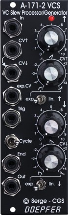
Vintage Edition |
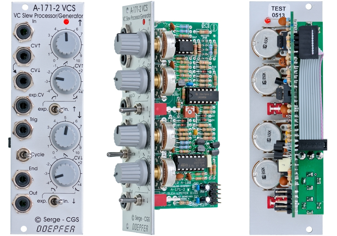
Module A-171-2 is a voltage controlled slew limiter with a lot of additional features beyond a simple slew limiter. It's mostly a licensed copy of Ken Stones VCS which is in turn based on the Serge VCS.
These are the most important features:
-
Manual control of the Slew-Up time
-
CV control of the Slew-Up time with polarizer
-
Switch for linear/exponential shape of the rising section of the response curve
-
Manual control of the Slew-Down time
-
CV control of the Slew-Down time with polarizer
-
Switch for linear/exponential shape of the falling section of the response curve
-
Signal input: the "to-be-slewed" signal
-
CV Up Input, affected by the CV Up Control and the corresponding exp./lin. switch
-
CV Down Input, affected by the CV Down Control and the corresponding exp./lin. switch
-
CV Up and CV Down sockets are normalled
-
exponential CV input: named "V/Oct" in the original design but as it's not really exactly 1V/Oct we named this input "exp.CV", mainly used for VCLFO/VCO applications in cycle mode or as common exponential control for both up and down times in slew mode
-
Trigger input: used for envelope generation or retrigger in VCLFO/VCO mode, a pulse at the trigger input will start the envelope or retrigger the VCLFO/VCO
-
End output: turns high as the output falls below about 20mV, turns low as the outputs goes beyond about 3.5V, in cycle mode a rectangle signal is generated
-
Cycle on/off switch: when "on" the End output is internally connected to the Trigger Input to generate cyclic signals like an VCLFO/VCO, max. frequency about 2.5kHz/3.5kHz (shape switches lin./exp.), max period about 15s/40s (shape switches lin./exp.)
-
Output: the signal output of the module
-
LED display: displays the slew limiter output signal
Typical applications:
-
VC Slew Limiter / VC Portamento / VC Low Pass Gate
Cycle switch = off, no trigger signal applied to Trig socket:
Voltage controlled Slew limiter or portamento generator: the signal applied to the signal input is "slewed". The slew up and down times are controlled manually by means of the Up and Down controls, the effect of the CV Up and CV Down control voltages are controlled by the CV Up and CV Down controls, in exponential mode these controls also affect the slew shape (see symbols at the CCW and CW positions of the controls)
If an audio signal is applied an short slew rates are chosen the module works as a simple VCF/VCA combo -
A/D Envelope Generator / Pulse Delay / Subharmonic Generator
Cycle switch = off, trigger signal applied to Trig socket, no input signal:
Simple Attack/Decay envelope Generator, the rise and fall times are controlled like the slew up/down times above, including the shape of the falling/rising slope of the envelope, the exp. CV input can be used to change both attack and decay simultaneously
At the End output a pulse appears as the end of the envelope is reached (less than about 20mV), this can be used as a pulse delay
If a series of triggers are applied to the VCS faster than the total rise and fall times, the module will divide the incoming signal by a whole number. In the audio range the output will be the sub-harmonic series. -
VCLFO / VCO
Cycle switch = on, no trigger signal applied to Trig socket, no input signal:
Voltage controlled LFO/VCO, the rise and fall times of the waveform are controlled like the slew up/down times above, including the shape of the falling/rising slope
the exp. CV input can be used like the CV input of a VCO or VCLFO, the response is exponential but not exactly 1V/oct
Additional information about the features of the module are available at Ken Stone's website Ken Stones VCS and the excellent analysis of the circuit by Tim Stinchcombe.
Additional specifications:
-
frequency range in Cycle mode and both switches to linear: about 15 seconds period up to0 2.5 kHz
-
frequency range in Cycle mode and both switches to exponential: about 45 seconds period up to 3 kHz
-
minimal rise/fall time in triggered mode (envelope generator) with both switches to linear or exponential: about 200us
-
maximal rise/fall time in triggered mode (envelope generator) with both switches to linear: about 10 seconds
-
maximal rise/fall time in triggered mode (envelope generator) with both switches to exponential: about 20 seconds
Breite/Width: 8 TE / 8 HP / 40.3 mm
Tiefe/Depth: 60 mm
(gemessen ab der Rückseite der Frontplatte / measured from
the rear side of the front panel)
Strombedarf/Current: +30mA (+12V) / -30mA (-12V)
Vintage Edition : Euro 155.00
The price in US$ depends upon the exchange rate between Euro and US$ at the payment day.