A-185-2 Precision CV Adder
|
|
|
 |
 |
|
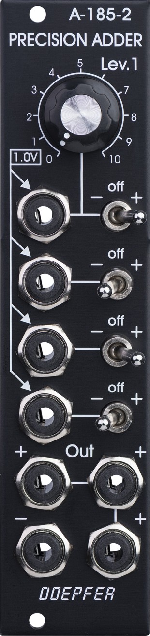
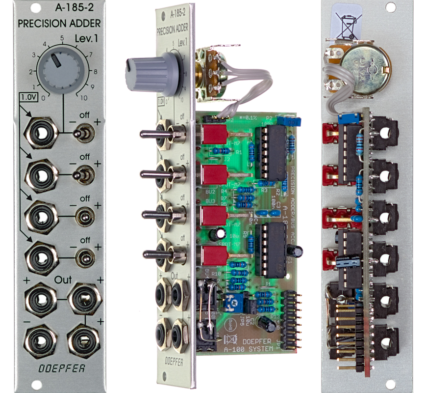
Standard Edition |
Vintage Edition |
Module A-185-2 is a precision control voltage adder/buffer. Precision means that the amplification of the inputs without attenuators is exactly 1.00 and is suitable to add control voltages for the pitch control of VCOs (e.g. from keyboard + sequencer 1 + sequencer 2). Summing resistors matched to 0.1% are used to obtain an accuracy of 0.1% for the added voltages.
The module is equipped with four CV inputs: one with attenuator and three without attenuator. Each input is normalled to +1 V (i.e. if no plug is inserted the input contributes 1 V to the sum appearing at the output).
The input with attenuator can be used for common modulations (e.g. from an LFO, ADSR, Theremin, Pitch-Bender) for all VCOs connected to the output. The Lev.1 control is used to adjust the depth of the modulation, the first switch selects the polarity of the modulation. If no signal is connected to the first socket the attenuator works as a (fine) tuning knob because a voltage in the range 0...+1V (right position of the switch) or 0...-1V (left position of the switch) is added to the CV output. The Lev.1 control uses a logarithmic potentiometer to obtain a fine resolution in the lower range when input #1 is used for modulation or as fine tune control.
The inputs without attenuators are planned to add control voltages coming out of keyboards, sequencers, Midi-to-CV interfaces, ribbon controllers or other CV sources that follow the 1V/oct standard. For example the CV of a keyboard can be used to transpose the CV coming from a sequencer, or the CV of a slow sequencer can be used to transpose the CV from a fast sequencer.
Each input is equipped with a three-position switch that determines if the corresponding voltage is added (right position), subtracted (left position) or if the input has no effect (center position). If no plug is inserted the corresponding switch works as an octave switch for the lower three sections as the default 1 V are added or subtracted to the output voltage according to the switch position. The first switch can be used to add a variable voltage to the sum output. The variable voltage is adjusted with the Lev.1 control and the knob works then as kind of a (fine) tuning control.
The module is equipped with 4 outputs: three non-invertíng and one inverting ouput. An internal jumper can be used to connect the non-inverted or inverted output to the CV line of the A-100 bus. That way the module can used to control several VCOs that are connected to the same bus board as the A-185-2 (same functionality as A-185-1).
Important Notes:
There is a pin header with three pins (labelled JP5) near the bus cable connector. If no jumper is installed there is no connection between the outputs of the A-185-2 and the CV line of the A-100 bus. In the lower position the normal CV output of the A-185-2 is connected to the CV line of the A-100 bus. In the upper position the inverted CV output of the A-185-2 is connected to the CV line of the A-100 bus.
The module comes with an installed jumper JP5, i.e. one has to remove the jumper if e.g. an A-190-1/2/3/4, A-185-1 or another A-185-2 is already connected to the CV line of the same bus board! If the A-185-2 should be used as CV source for the A-100 bus the CV connection of another CV source (e.g. A-185-1 or A-190-1/2/3 or another A-185-2) has to be removed. Otherwise a short circuit is made between the outputs of the CV transmitters ! Please refer also to the technical notes concerning A-100 bus principles:
Do not insert patch cables into the CV input sockets while the other end of the cable is open. The A-185-2 features high impedance inputs. Cables with open ends will cause random voltages. The other end of each patch cable must be connected to a voltage (e.g. sequencer CV output, USB/Midi-to-CV interface CV output, LFO output, ADSR output, Theremin CV output, ribbon controller CV output and so on).
The following document shows the positions and functions of the jumpers and trimming potentiometers of the module: A185_2_trimming_potentiometers_and_jumpers.pdf. Pay attention that faulty adjustments caused by the user are not covered by warranty. In this case the working time required to re-establish the correct adjustment has to be charged.
Breite/Width: 6 TE / 6 HP / 30.0 mm
Tiefe/Depth: 50 mm (gemessen
ab der Rückseite der Frontplatte / measured from the rear side of the front
panel)
Strombedarf/Current: +10mA (+12V) / -10mA
(-12V)
Vintage Edition : Euro 95.00
The price in US$ depends upon the exchange rate between Euro and US$ at the payment day.