A-101-3 Modular Vactrol Phase Filter
nicht mehr lieferbar / no
longer available
click to enlarge |
|
http://blog.andreaskrebs.de/2010/06/27/doepfer-a-101-3-modular-12-stage-vactrol-phaser-example/
Das Modul A-101-3 ist ein 12-stufiger
Phase-Shifter, der mit sog. Vactrols als phasenschiebende Elementen arbeitet.
Vactrols sind bekannt für Ihren weichen und verzerrungsarmen Klang. Falls Sie
mehr über Vactrols wissen wollen, so finden Sie detaillierte Informationen auf
der Seite Vactrol Grundlagen.
Im Gegensatz zu anderen Phasern bietet der A-101-3 eine Reihe von Features, die
in dieser Form bei keinem anderen Phaser verfügbar sind. Der grundsätzliche
Unterschied besteht darin, dass der A-101-3 Zugriff auf alle Ein- und Ausgänge
der 12 Phaserstufen bietet. Durch die freie Verschaltungsmöglichkeit aller Ein-
und Ausgänge sind völlig neue Filter möglich, die auf keine andere Weise
realisierbar sind. Insbesondere die Möglichkeit frei patchbarer
Rückkopplungsschleifen (d.h. es nicht nur eine, sondern gleichzeitig mehrere
möglich) innerhalb der 12 Stufen, verbunden mit der Möglichkeit positiver oder
negativer Rückkopplung mit Hilfe der beiden Polarizer führt zu völlig neuen
Filtertypen (ein Polarizer ermöglicht positive oder negative Verstärkung in
dem Sinn, dass unter negativer Verstärkung eine Invertierung des Signals
verstanden wird, näheres hierzu finden Sie bei den Modulen A-133
VC Polarizer und A-138c Polarizing Mixer). Die
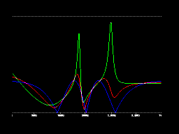
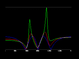
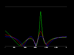
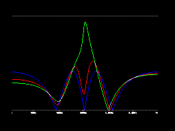
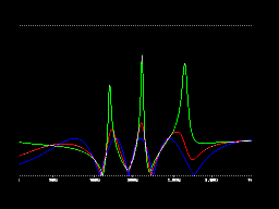
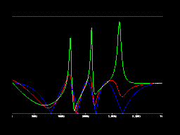
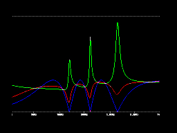
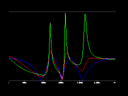
Frequenzkurven am Ende der Seite zeigen einige Beispiele, welche Filtertypen mit
diesem Konzept möglich sind.
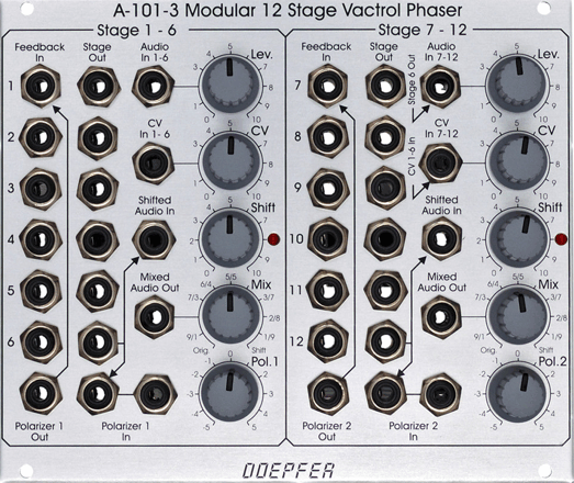
Intern besteht das Modul aus zwei Einheiten mit je 6 Phasenschieber-Stufen (1-6
bzw. 7-12), die über getrennte Audio-Eingänge (mit Abschwächern), getrennte
Audio-Ausgänge (mit Mixer-Stufen) und getrennte Phasenverschiebungs-Steuerungen
verfügen. Die Phasenverschiebungen sind manuell und über externe
Kontrollspannungen steuerbar, um die Phasen z.B. mit LFO, ADSR,
Zufallsspannungen, Theremin, MIDI-to-CV, Fußregler, Sequencer oder andere
Modulationsquellen zu steuern. Jede Einheit verfügt über eine LED zur Anzeige
der Phasenverschiebung der betreffenden Einheit (die LEDs sind in Serie mit den
Vactrol-LEDs geschaltet und zeigen damit gleichzeitig die Vactrol-Leuchtstärken
an).
Jede der 12 Phasenschieber-Stufen besitzt eine Audio-Ausgangsbuchse und eine
Feedback-Eingangsbuchsen, um volle Flexibilität bei der Verschaltung für
verschiedene Filtertypen zu erhalten. Das Audio-Eingangssignal und das
Audio-Ausgangssignal der Stufen 6 bzw. 12 werden in 2 Mixern gemischt, um auf
Wunsch zwei getrennte Audiosignale zu erhalten (für den normalen Phaser-Effekt
werden Eingangs- und Ausgangssiganl 50:50 gemischt). Die beiden Submodule sind
intern über normalisierte Buchsen verbunden, so dass zwei 6-stufige Phaser
ohne zusätzliche Patches möglich sind: Audio-Ausgang 6 ist normalisiert auf
Audio-Eingang 7, der CV-Eingang 1-6 ist normalisiert auf CV-Eingang 7-12. Auf
Grund der offenen Struktur können jedoch alle mit Hilfe der Schaltbuchsen
erzeugten Verschaltungen geändert werden (z.B. andere Phaserstufen als 6 bzw.
12 für die Ausgangsmixer: hierzu wird einfach der Ausgang einer anderen Stufe
auf den Mixer-Eingang gepatcht). Die interne Verschaltung des Moduls zeigt das
folgende Blockschaltbild:
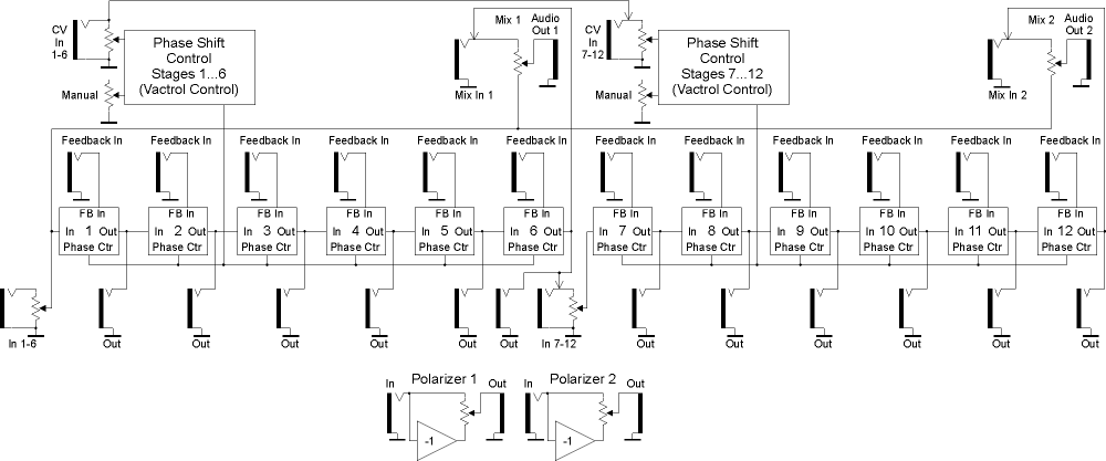
A-101-3 Blockschaltbild
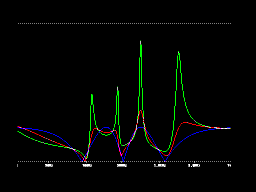
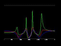
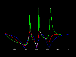
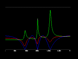
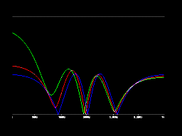
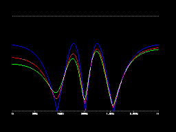
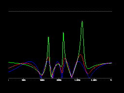
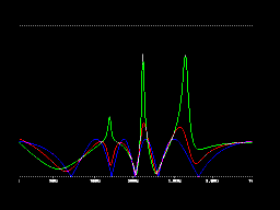
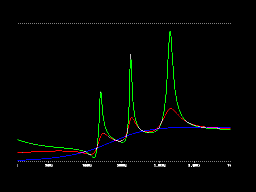
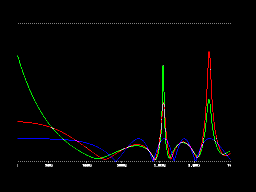
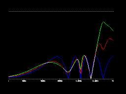
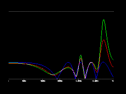
Am Ende der Seite finden Sie eine Reihe von Frequenzgang-Kurven, die die zahlreichen Möglichkeiten des Moduls deutlich machen:
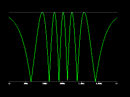
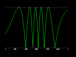
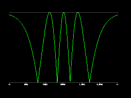
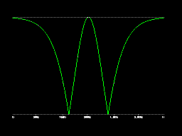
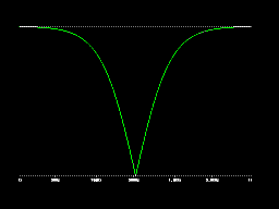
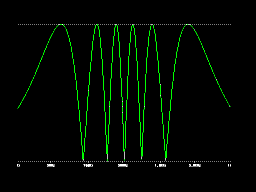
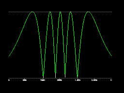
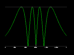
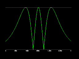
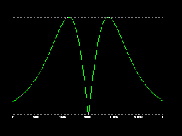
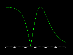
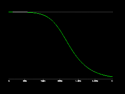
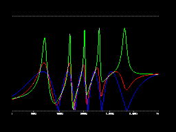
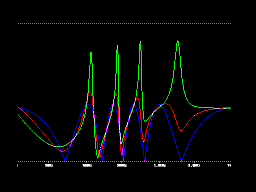
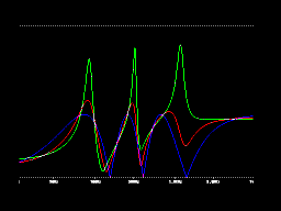
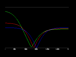
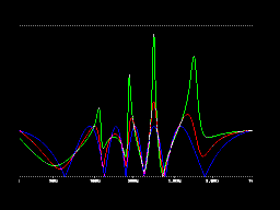
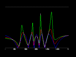
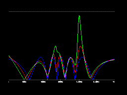
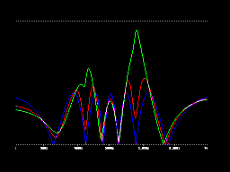
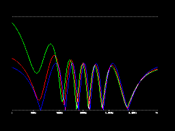
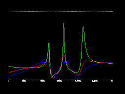
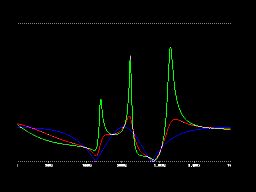
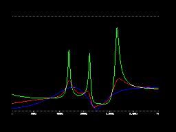
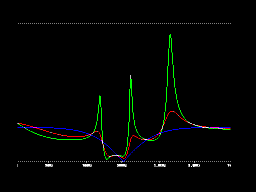
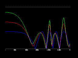
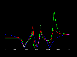
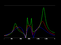
Die erste Gruppe der 12 Kurven zeigen den Frequenzgang wenn die Stufen 1...12 als Eingang für den Ausgangsmixer verwendet werden (keine Rückkopplungen und keine sonstigen Patches). Dies ist die Standard-Phaserschaltung mit unterschiedlicher Anzahl von Phaserstufen. Die Bilder zeigen, dass die Zahl der Kerben des entstehenden Kammfilters von der Zahl der verwendeten Phaserstufen abhängt. Die Kerben bewegen sich durch das Audiospektrum, wenn die Phasenverschiebung geändert wird (manuell oder mit Hilfe einer externen Steuerspannung, beim Standard-Phaser wird meist der Dreieck- oder Sinusausgang eines LFOs zur Modulation verwendet). Die Zahl der Kerben berechnet sich nach folgendem Schema: Zahl der Kerben = Ganzzahl (Zahl der Phaserstufen/2). Eine ungerade Zahl von Stufen führt zu einem asymmetrischen Verhalten am oberen und unteren Ende des Spektrums (oben: Hochpassverhalten, unten: Durchlass). Eine gerade Zahl von Stufen führt zu einem identischen Verhalten am oberen und unteren Ende des Spektrums (oben und unten Durchlass). Verwendet man nur Stufe 1 erhält man einen Hochpass, Stufe 2 ergibt ein Notch-Filter.
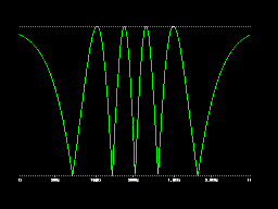
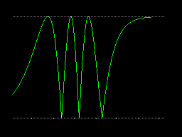
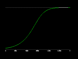
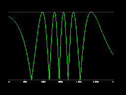
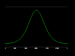
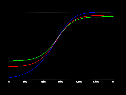
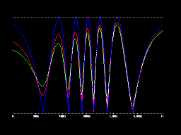
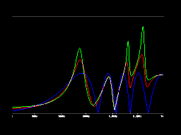
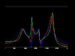
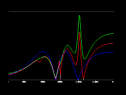
Die zweite Gruppe zeigt das Frequenzverhalten, wenn ein Inverter zwischen der Phaserstufe und dem Mixer eingefügt wird (einer der Polarizer kann z.B. hierfür verwendet werden). Das Ergebnis ist ein invertierter Frequenzgang gegenüber der ersten Gruppe, z.B. Tiefpass für Stufe 1, Bandpass für Stufe 2 usw. Der Frequenzgang ergibt sich aus dem betreffenden Bild der ersten Gruppe jeweils durch Spiegelung an der horizontalen Achse.
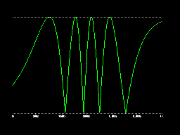
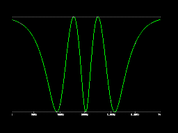
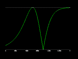
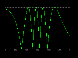
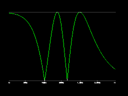
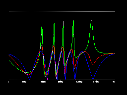
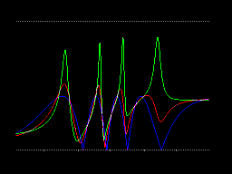
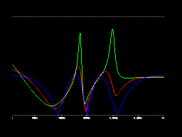
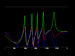
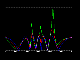
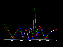
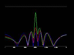
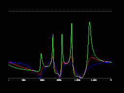
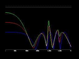
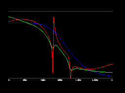
Zusätzliche Rückkopplung färbt den Klang (ähnlich der Resonanz/Emphasis-Funktion bei normalen Filtern). Die dritte Gruppe zeigt Frequenzgänge mit einer Rückkopplungsschleife. Für die Rückkopplung auf Stufe 1 wird immer die gleiche Stufe verwendet, die auch als Ausgangsstufe zum Einsatz kommt (Beispiel: wird Stufe 11 als Ausgang verwendet, so erfolgt wird die Rückkopplung von Stufe 11 auf Stufe 1).
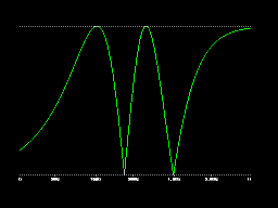
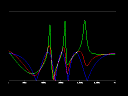
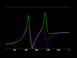
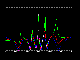
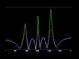
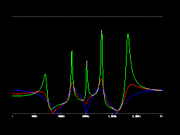
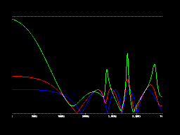
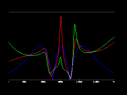
Es ist jedoch nicht zwingend, die gleiche Stufe für die Rückkopplung zu verwenden, die als Ausgangsstufe benutzt wird. Die Gruppen 4, 5 and 6 zeigen das Verhalten mit verschiedenen Rückkopplungsschleifen (feedback loops). In Gruppe 4 wird beispielsweise immer der Ausgang 12 als Audio-Ausgang verwendet, die Rückkopplung erfolgt jedoch von den Stufen 12, 11, 10, 9 usw. Gruppe 5 ist ähnlich, jedoch wird Stufe 6 als Audio-Ausgang verwendet. In Gruppe 6 ist die Ausgangsstufe der veränderliche Parameter, die Rückkopplung erfolgt immer von Stufe 8 zu Stufe 1 für alle Filter.
Als Ergebnis aus all diesen Kurven lässt sich folgendes festhalten:
-
Die Zahl der Kerben (notches) wird von der Zahl der verwendeten Stufen bestimmt: Zahl der Kerben = Ganzzahl (Zahl der Phaserstufen/2)
-
Die Zahl der Resonanz-Peaks wird bestimmt von der Zahl der verwendeten Phaserstufen für die Rückkopplung: Zahl der Peaks = Ganzzahl (Zahl der Phaserstufen/2)
-
Die Höhe der Resonanz-Peaks wird von der Rückkopplungsstärke bestimmt
Durch das offene Konzept des Moduls sind unterschiedliche Zahlen von Kerben und Peaks möglich, indem man den entsprechenden Patch für die gewünschte Anzahl von Kerben und Peaks verwendet !
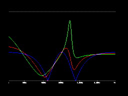
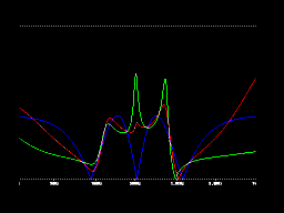
Last but not least ermöglicht die offene Struktur des Moduls auch mehrfache Rückkopplungsschleifen (z.B .Stufe 8 auf 3 und Stufe 6 auf 1 gleichzeitig) und sogar "Vorwärts-Schleifen" (z.B. von Stufe 5 auf 9). In Kombination mit den beiden Polarizern kann die Polarität für die Rückkopplung normal oder invertiert gewählt werden, was zu weiteren Effekten und neuen Filterkennlinien führt. Einige Beispiele für mehrfache und Vorwärts-Schleifen finden Sie in der letzten Gruppe der Frequenzgangkurven. Beachten Sie, dass für einige Beispiele eine Veränderung der Rückkopplungsstärke auch zum "Wandern" der Peaks relativ zu den Kerben führt ! Mit Hilfe von VCAs (A-130, A-131, A-132) oder des spannungsgesteuerten Polarizers A-133 können die Rückkopplungen natürlich auch spannungsgesteuert werden.
Die deutsche Bedienungsanleitung ist als PDF-Datei
auf unserer Website verfügbar: ![]() A1013_Anl.pdf.
A1013_Anl.pdf.
click to enlarge |

|
Module A-101-3 is a 12 stage phase shifter with vactrols as phase
shifting elements. Vactrols are known for their smooth sound behaviour. For more
general details about vactrols please look at the Vactrol
Basics page.
In contrast to other phaser designs the A-101-3 is much more flexible and
offering a lot of new features not available from other phasers on the market
(as far as we know, please tell us if we are wrong). The main difference is that
our design offers access to each of the 12 input and output stages leading to a
lot of new filters that cannot be obtained in other ways. Especially the free
patchable feedback loops (yes, not only one feedback loop is
possible) between each of the 12 stages, the separate phase shift control for
the stages 1-6 and 7-12, and the 2 polarizers intended to control the feedback
loops lead to completely new filter types (a polarizer is a circuit that is able
to generate positive and negative amplifications in the range -1...0...+1 with
-1 = inversion, 0 = full attenuation, +1 = unchanged signal, for details
concerning the polarizer function please look at the A-133 VC Polarizer
or A-138c
Polarizing Mixer module).
The module sketch and the frequency response curves below will help to explain
the outstanding functions of the module:
Internally the module is made of 2 independent 6 stage phase shifters (1-6 reps.
7-12) with separate audio inputs (with attenuators), audio outputs (with mix
control), and phase shift control units. The phase shift control units feature
both manual and voltage controlled phase shifting (e.g. from a LFO, ADSR, Random
Voltage, Theremin CV, Foot Controller CV ...). For each sub-module a phase shift
display (LED) is available. The LED shows the illumination state of the 6
vactrols of the sub-module in question as it is connected in series with the
internal vactrol LEDs.
Each of the 12 phase shift states is equipped with an audio output socket and
feedback input socket to obtain full flexibility to create a multitude of
different filters. The audio input signal and the output signals of stage 6
resp. stage 12 are mixed with 2 manual controls to obtain effects at two audio
outputs (for normal phase shifting effect this is 50% input signal and 50% phase
shifted signal). The two submodules are internally connected via normalized
sockets so that two 6 stage phase shifters can be obtained without external
patches. Audio output of stage 6 is normalized to audio input of stage 7 and CV
input 1-6 is normalized to CV input 7-12. But due to the open structure of the
module even other stages than stage 6 and stage 12 can be used as outputs to
generate different sounds (simply patch the desired stage output to the
normalized mix input socket).
For a better understanding of the outstanding features a table with frequency response graphs is added at the end of this document.
The first 12 frequency response curves show the behaviour of the module when stages 1...12 are used as outputs for the final mixer (no feedback, no additional patching). This is the standard phaser application with a different number of phase shift stages. The frequency response curves of the higher stages show the typical comb filters of a phaser. The notches move through the audio spectrum as the manual phase shift control is operated or a control voltage is applied (for a standard phase shifter this is normally the triangle or sine wave from a LFO). The number of notches increases with the number of stages: number of notches = integer of number of stages/2. Odd stage numbers lead to different behaviours in the higher and lower frequencies (low end: high pass behaviour, high end: passage). Even stage numbers show the same response in the higher and lower frequencies (passage for both). Stage 1 is nothing but a high pass filter, stage 2 is the standard notch filter.
The second 12 frequency response curves show the behaviour when an inverter is inserted between the stage output in question and the final mixer (one of the polarizers can be used for this job). The result is the inverse frequency response compared to the output without inverter: e.g. low pass for stage 1, band pass for stage 2. The resulting frequency response curve is simply obtained by vertical mirroring the first 12 curves.
Additional feedback colors the sound. The third 12 frequency response curves show the behaviour of the filters with one feedback loop. Feedback comes from the stage used as output back to stage 1 (e.g. if stage 11 is used, feedback from stage 11 to stage 1).
But it is not imperative to use the same stage for feedback and audio output. Groups 4, 5 and 6 of frequency response curves show the behaviour with different feedback loops. In group 4 the same output 12 is used for all graphs but but the feedback goes from stage 12, 11, 10, 9 ... and so on back to stage 1. Group 5 is nearly the same but output 6 is used for all graphs. In group 6 the output stage is the varying parameter and the feedback goes from stage 8 to 1 for all filters.
This is the result from all the response curves:
-
The number of notches is defined by the number of stages used as output (number of notches ~ stage number/2)
-
The number of resonance peaks is defined by the number of stages used for feedback (number of peaks ~ number of feedback stages used/2)
-
The height of the peaks is determined by the amount of resonance
Different numbers of notches and peaks are possible by using the corresponding patch for output in use and feedback loop !
Last but not least the open structure of the module allows multiple feedback loops (e.g. stage 8 to 3 and stage 6 to 1 simultaneously) and even "forward" loops (e.g. from stage 5 to stage 9). In combination with polarizers additionally the feedback or the output polarity can be normal or inverted. This leads to a multitude of possible filter types. Some examples for multiple and forward loops are shown in the last section of the response curves. Pay attention that for some examples e.g. varying the feedback leads to "moving" peaks. By means of VCAs (A-130, A-131, A-132) or the voltage controlled polarizer A-133 the feedbacks can be voltage controlled.
For more detailed information please look at the
English user's manual ![]() A1013_man.pdf
A1013_man.pdf

A-101-3 Sketch
Tiefe/Depth: 65 mm (gemessen ab der Rückseite der Frontplatte / measured from the rear side of the front panel)
Strombedarf/Current: +50mA (+12V) / -50mA (-12V)
nicht mehr lieferbar / no longer available
