A-101-8 Photo Phasing
Unser Kunde Markus Horn hat die
neuen Module 101-8, A-135-5, A-147-4 und A-171-4 getestet und dazu einen
ausführlichen Bericht verfasst, der im Synthesizer-Magazin
#98 im August 2023 erschienen ist.
Die folgenden beiden Videos dienen zur Veranschaulichung des Geschriebenen:
https://youtu.be/4_BHqh5DJKg (A-101-8 + A-135-5 + A-171-4)
und
https://youtu.be/o8EN6e3066s
(A-147-4)
Our customer Markus Horn tested
the new modules 101-8, A-135-5, A-147-4. A detailed report has been be published in
the Synthesizer-Magazin #98 in August 2023 (in German language).
These are the related videos: https://youtu.be/4_BHqh5DJKg (A-101-8 + A-135-5 + A-171-4)
und
https://youtu.be/o8EN6e3066s
(A-147-4)
Weitere Demos / more demos:
https://youtu.be/keaWlsK7ZD8 (A-101-8 demo without speaking)
https://www.youtube.com/watch?v=RQFquz8hg5M (Sonic State Superbooth
2023)
https://youtu.be/vq92HaIXgDY (proaudio Superbooth 2023)
| click to enlarge |
click to enlarge |
 |
 |
|
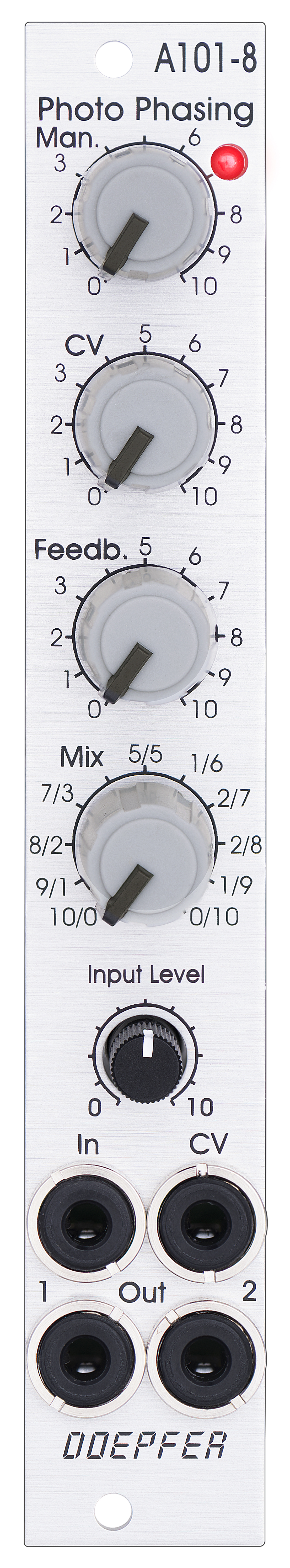
Standard Edition |
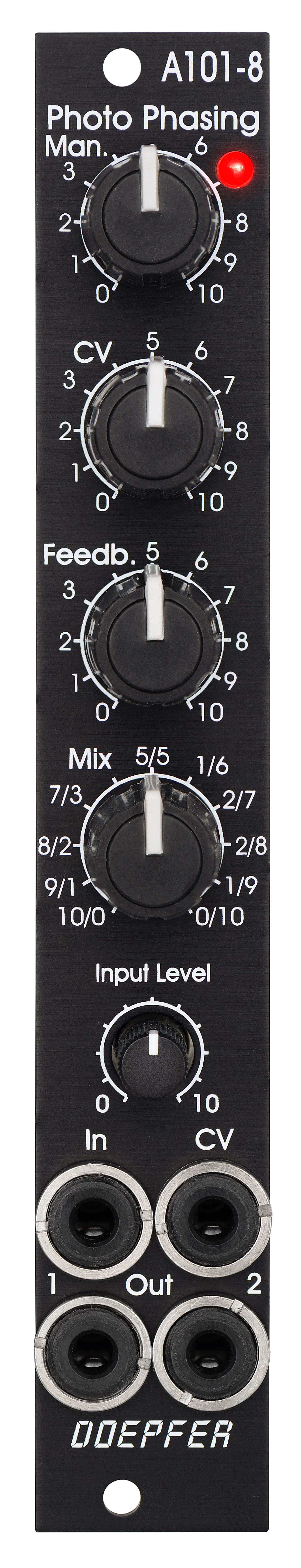
Vintage Edition |
Das Modul verfügt über folgende Bedien- und Anzeigeelemente sowie Ein/Ausgänge:
-
Regler Man. : manuelle Einstellung des Phasing-Offsets (Basiswert)
-
Regler CV: Abschwächer für die am CV-Eingang anliegende Steuerspannung
-
Regler Feedb.: Rückkopplung (ähnliche Funktion wie bei Filtern die Resonanz)
-
Regler Mix: Mischungsverhältnis zwischen Original und Effektsignal an Ausgang 1
-
bei Linksanschlag erscheint nur das modifizierte Eingangssignal (siehe Hinweis unten *)
-
in Mittelstellung erscheint eine Mischung aus modifiziertem Eingangssignal und dem phasenverschobenen Signal (das ist die Standard-Position für den Phasing-Effekt)
-
bei Rechtsanschlag erscheint das reine phasenverschobene Signal (z.B. für Vibrato-Effekte)
-
-
Regler Input Level: Abschwächer für das an der Buchse In anliegende Audio-Eingangssignal
-
Buchse In: Audio-Eingang
-
Buchse CV: Steuerspannungs-Eingang
-
Buchse Out 1: Audio-Ausgang Mix-Signal
-
Buchse Out 2: Audio-Ausgang modifiziertes Eingangssignal (siehe Hinweis unten *)
-
LED: optische Anzeige der Phasenverschiebung
Wie beim Vorbild gibt es auch bei dem Modul einige Besonderheiten:
-
Das Eingangssignal durchläuft in der Schaltung zunächst eine Vorstufe, an deren Ausgang ein "modifiziertes" Eingangssignal (*) anliegt. Dieses hat zwar die Phasenschieber-Kette noch nicht durchlaufen, wird aber von der Feedback-Funktion bereits beeinflusst. Nur wenn Feedback auf Null steht liegt hier das unveränderte Eingangssignal an. Andernfalls sind bereits Komponenten des Rückkopplungs-Signals enthalten.
-
Dieses Signal liegt an der Buchse Out 2 an.
-
Verwendet man die beiden Buchsen Out 1 und Out 2 für zwei Stereo-Kanäle, so ergibt sich damit ein räumlicher Stereo-Effekt.
-
Das gleiche Signal wird auch für den Links-Anschlag des Mix-Reglers verwendet. Bei Linksanschlag des Mix-Reglers erscheint das unveränderte Eingangssignal also nur dann, wenn der Feedback-Regler auf Null steht. Andernfalls sind bereits Komponenten des Rückkopplungs-Signals enthalten.
-
Das Vorbild hatte zwei verschiedene Audio-Eingänge: eine 5-polige DIN-Buchse und eine 6,3mm-Klinkenbuchse. Die DIN-Buchse war für hoch-pegelige Line-Signale vorgesehen. Wurde die 6,3mm-Klinkenbuchse genutzt, so erhöhte sich beim Einstecken des Klinkensteckers die Verstärkung ca. um den Faktor 100. Diese Buchse war daher für nieder-pegelige Signale (z.B. E-Gitarre oder Mikrofon) vorgesehen. Beim A-101-8 ist stattdessen eine Steckbrücke vorhanden, mit der man zwischen den beiden Verstärkungen wählen kann. Beim Einsatz innerhalb des A-100 bleibt es üblicherweise bei der niedrigen Verstärkung, da im A-100 die Signale i.d.R. annähernd Line-Pegel besitzen. Andernfalls kann es zu Verzerrungen kommen.
-
Die 8 Photowiderstände und LEDs befinden sich innerhalb eines lichtdichten Gehäuses. Zusätzlich sind die Leiterplatten des Moduls aus licht-undurchlässigem schwarzen Material gefertigt, um eventuell störendes Licht von benachbarten Modulen oder der Busplatine weitgehend auszuschließen.
Das folgende Dokument zeigt
die Positionen und Funktionen der Trimmpotentiometer und Steckbrücken: A101_8_trimming_potentiometers_and_jumpers.pdf
Wir weisen vorsorglich darauf hin, dass falsche Justierungen durch das
Verändern der Trimmpotentiometer-Einstellungen seitens des Kunden nicht
von der Garantie abgedeckt sind. In diesem Fall müssen wir ggf. die
Arbeitszeit für die Neujustierung des Moduls in Rechnung stellen !
The module has these controls and in/outputs available:
-
Control Man. : manual control of the phase shift offset (base value)
-
Control CV: attenuator for the signal applied to the CV socket
-
Control Feedb.: Feedback or Resonance (similar function as filter resonance/feedback/emphasis)
-
Control Mix: sets the mixing ratio between original and phase shift signal appearing at output 1
-
fully CCW: only the modified input signal appears at output 1 (see note below *)
-
center: a mixture between the modified input signal and the phase shift signal appears at output 1, that's the standard position for the classical phasing effect
-
fully CW: the pure phase shifted signal appears at output 1 (e.g. for vibrato effects)
-
-
Control Input Level: attenuator for signal applied to the In socket
-
Socket In: audio input
-
Socket CV: control voltage input
-
Socket Out 1: audio output 1 (mix signal)
-
Socket Out 2: audio output 2 (modified input signal)
-
LED: visual control of the phase shift
The module has some peculiarities (same as the historic model):
-
The input signal is processed at first by a pre-stage which outputs a "modified" input signal (*). This signal is not processed by the phase shift stages but is affected by the feedback setting. Only when feedback is set to zero this signal is identical to the input signal. Otherwise it contains feedback components.
-
This signal is output on socket Out 2.
-
When both output sockets Out 1 and Out 2 are used as stereo channels one obtains a spatial stereo sound effect.
-
The same signals is also used for the CCW position of the mix control. With mix control fully CCW the unmodified signal appears only if the feedback control is set to zero. Otherwise it contains feedback components.
-
The historic model had two audio inputs: one 5-pin DIN socket and a 1/4" jack socket. The DIN socket was intended for high-level line signals. When the 1/4" jack socket was used the amplification of the pre-stage increased by about 100. The 1/4" jack socket was intended for low level signals (e.g. electric guitars or microphones). For this feature the A-101-8 has an internal jumper that can be used to increase the amplification. As long as the module is used within the A-100 system usually the lower amplification is used to avoid distortion.
-
The 8 photo resistors and LEDs are assembled within an small lighproof box. In addition the pc boards are made of lighproof black material to avoid interfering light from other modules or the bus board.
The following document shows the
positions and functions of the jumpers and trimming potentiometers of the module:
A101_8_trimming_potentiometers_and_jumpers.pdf
Pay attention that faulty adjustments caused by the user are not
covered by warranty. In this case the working time required to
re-establish the correct adjustment has to be charged.
Breite/Width: 4 TE / 4 HP / 20.0 mm
Tiefe/Depth: 45 mm (gemessen ab der Rückseite der Frontplatte / measured
from the rear side of the front panel)
Strombedarf/Current: +30 mA (+12V) / -30 mA
(-12V)
Standard Version : Euro 145.00
Vintage Edition : Euro 155.00
The price in US$ depends upon the exchange rate between Euro and US$ at the payment day.