A-121d Dual Multimode Filter
|
click to enlarge |
click to enlarge |
 |
 |
|
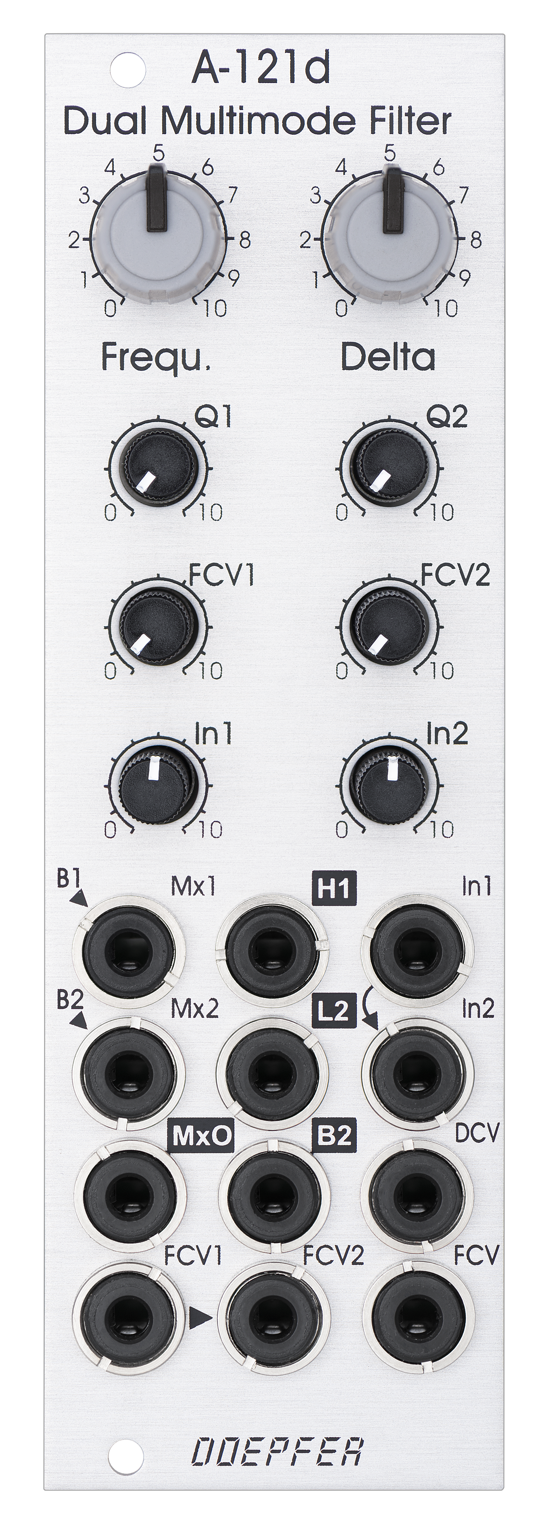
Standard Edition |
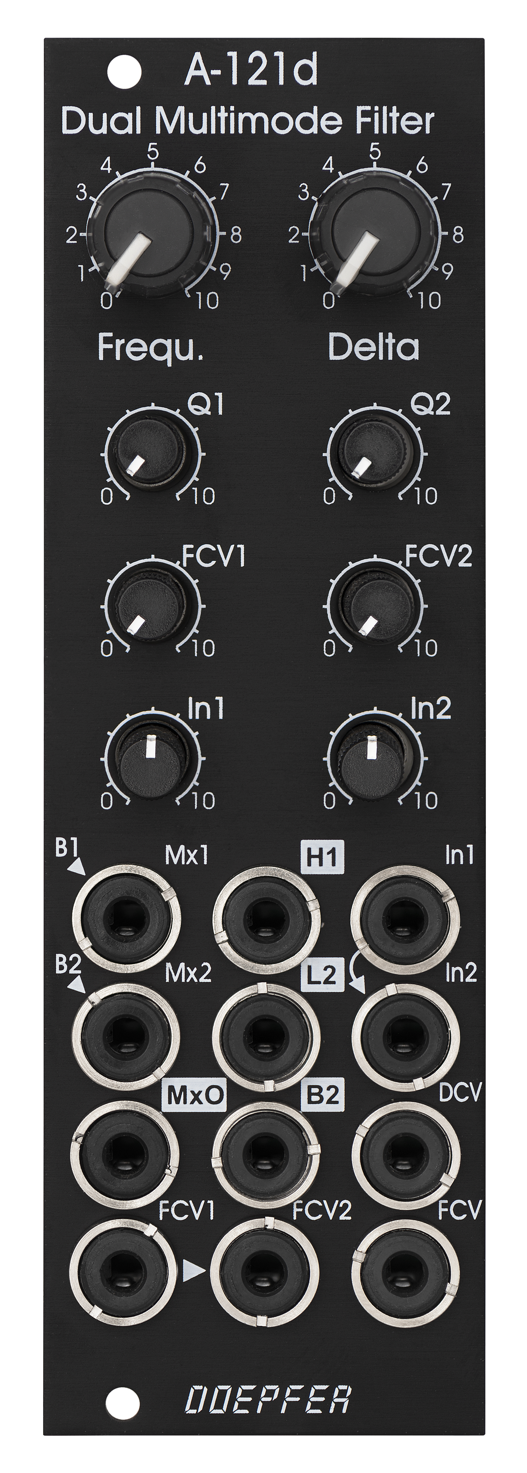
Vintage Edition |
Das Modul A-121d ist ein spezielles zweifaches
Multimode-Filter, das als parallel oder
seriell geschaltetes Doppel-Filter eingesetzt werden kann. Aber auch
Stereo-Anwendungen sind denkbar. Die Filter
basieren auf zwei speziellen Schaltungen, wobei eines der beiden Filter Bandpass und
Hochpass, das andere Bandpass und Tiefpass zur Verfügung stellt. Es handelt
sich um ein neues Filter-Design, das bisher bei keinem unserer Filter-Module zum
Einsatz kommt.
Bei den Bedienelementen und CV-Eingängen für die
Steuerung der Filter wurde speziell auf die Anwendung als Doppel-Filter Wert
gelegt: für die Steuerung der Frequenzen steht ein gemeinsamer Frequenz-Regler
(Frequ.)
und ein Differenz-Regler (Delta) zur Verfügung, mit dem der Abstand zwischen den Frequenzen der beiden Filter
von Hand eingestellt werden kann. Beide Parameter sind auch über externe
Steuerspannungen (FCV, DCV) einstellbar. Der Eingang FCV hat eine
Empfindlichkeit von ca. 1V/Oktave. Die Parameter Resonanz (Q1, Q2), die
Empfindlichkeit des
individuellen Frequenz-Steuereingangs (FCV1, FCV2) und die Pegel des Audio-Eingangs
(In1, In2) werden über die entsprechenden Regler
getrennt eingestellt.
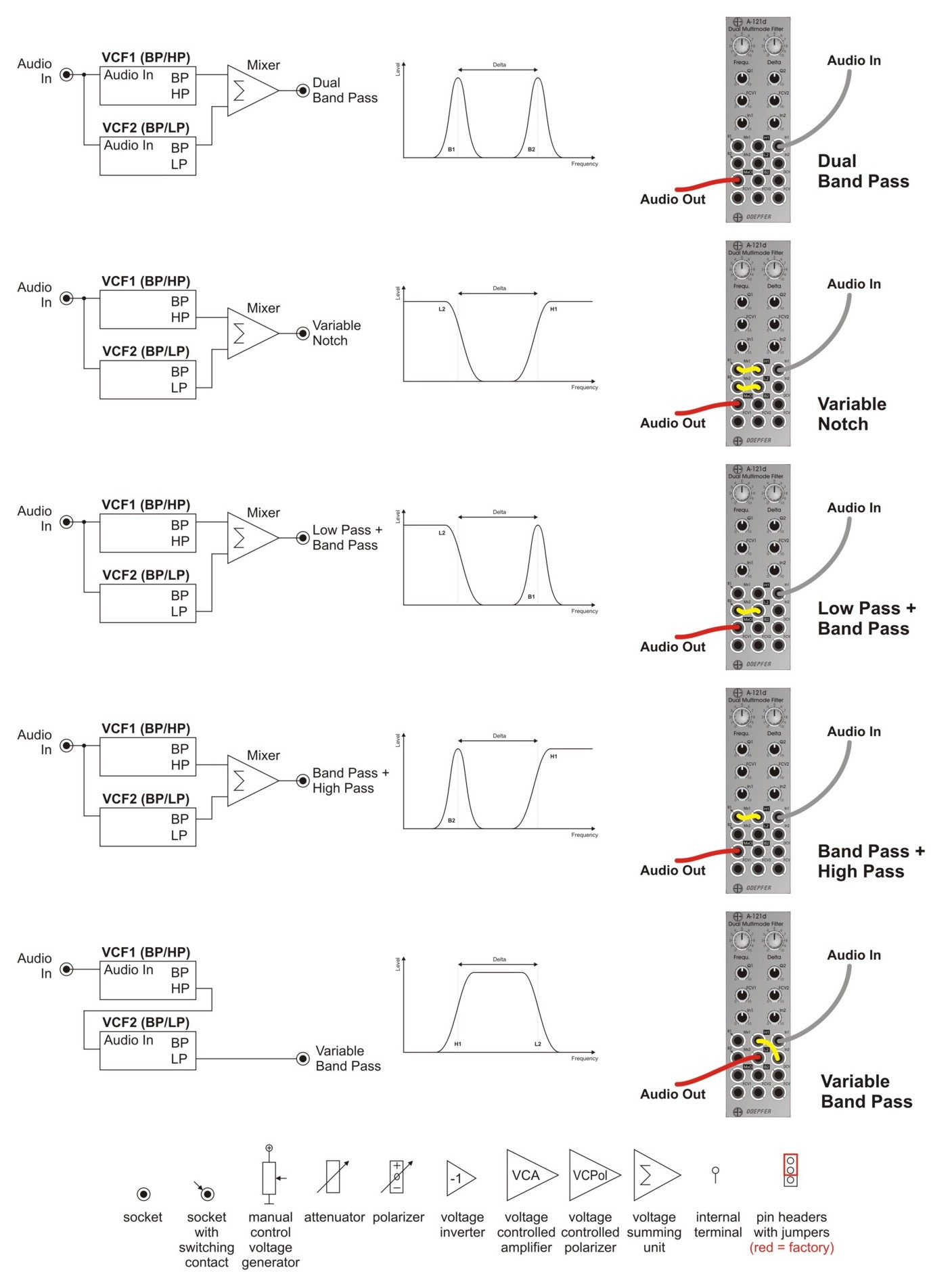
Das Modul verfügt über eine einfache Mix-Einheit mit den Eingängen Mx1 und
Mx2, sowie dem Ausgang MxO. Werden die Buchsen Mx1 und Mx2 nicht beschaltet, so
sind diese über die Schaltkontakte mit den Signalen B1 (Bandpass 1) und B2
(Bandpass 2) verbunden (wird auch als "normalisiert" bezeichnet). Alle
anderen Filter-Kombinationen werden durch Verpatchen der Filter-Ausgänge (H1 =
Hochpass 1, L2 = Tiefpass 2) mit der Mix-Einheit realisiert (siehe
Übersicht zu allen Möglichkeiten weiter unten).
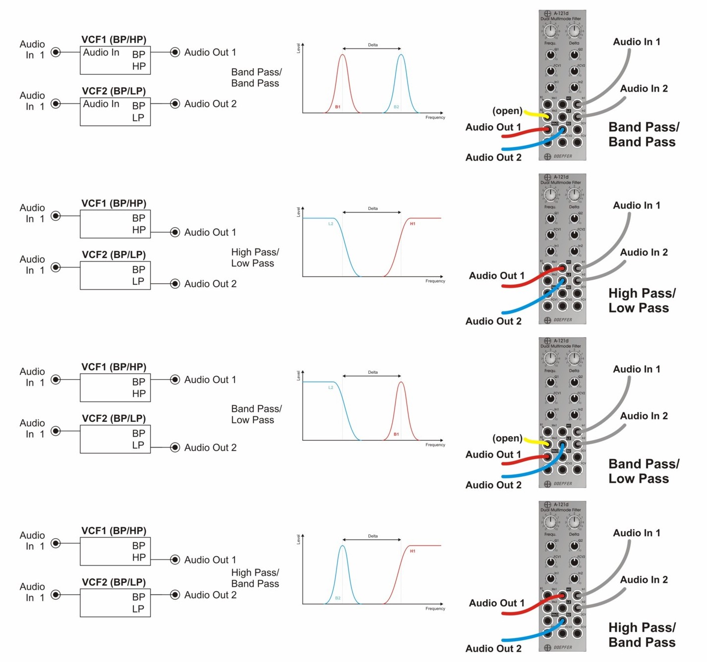
Es können zwei (oder auch mehr) Module kaskadiert werden, um beispielsweise 4
(oder mehr) parallel geschaltete spannungsgesteuerte Bandpässe zu realisieren.
Regler:
-
Frequ.: gemeinsamer Frequenz-Regler für beide Filter
-
Delta: steuert manuell die Differenz zwischen den Frequenzen der beiden Filter (Frequency Spread), in Mittelstellung sind die Frequenzen annähernd gleich (sofern auch alle anderen Frequenz-Steuerungsparameter sich in neutralen Stellungen befinden)
-
Q1 / Q2: Resonanz-Regler für Filter 1 und 2
-
FCV1 / FCV2: Abschwächer für die individuellen Frequenz-Steuereingänge FCV1 (Filter 1) und FCV2 (Filter 2)
-
In 1 / In 2: Abschwächer für die Audio-Eingänge von Filter 1 und 2.
Buchsen:
-
Mx1 / Mx2: Audio-Eingänge des Mixers, Mx1 ist normalisiert auf Bandpass 1 (B1), Mx2 ist normalisiert auf Bandpass 2 (B2)
-
MxO: Audio-Ausgang des Mixers
-
In1 / In2: Audio-Eingänge für Filter 1 und 2, In2 ist normalisiert auf In1, so dass das gleiche Audio-Signal beiden Filtern zugeführt wird, wenn In2 nicht beschaltet wird.
-
H1: Hochpass-Ausgang Filter 1
-
L2: Tiefpass-Ausgang Filter 2
-
B2: Bandpass-Ausgang Filter 2
-
DCV: Steuerspannungs-Eingang für die Frequenz-Differenz (Delta) der beiden Filter
-
FCV1 / FCV2: individuelle Frequenz-Steuereingänge für Filter 1 und 2, laufen über die Abschwächer FCV1 und FCV2, die Buchse FCV2 ist normalisiert auf die Buchse FCV1
-
FCV: gemeinsamer Frequenz-Steuereingang für beide Filter, ca. 1V/Oktave
Die Dreieck-Symbole auf der Frontplatte markieren die Normalisierungen der Buchsen (B1>Mx1, B2>Mx2, In1>In2, FCV1>FCV2). Die vier Ausgänge des Moduls sind invers beschriftet.
Technische Hinweise:
- Ab Werk ist das Modul so eingestellt, dass die Resonanz der beiden Filter nicht bis zur Eigenresonanz reicht. Mit Hilfe von zwei Trimmpotentiometern können die Filter vom Benutzer aber so eingestellt werden, dass Eigenresonanz erreicht wird, falls das gewünscht ist. Auf diese Weise kann das Modul als Dual-VCO eingesetzt werden. Die Qualität der Sinus-Kurvenform hängt der Einstellung des betreffenden Trimmpotentiometers ab und kann bei entsprechender Einstellung auch deutlich von der Sinus-Form abweichen.
- Für den Differenz-Steuereingang DCV steht ein internes Trimmpotentiometer als Abschwächer zur Verfügung, um die Empfindlichkeit für diesen Steuereingang einstellen zu können .
- Über entsprechend gesetzte Jumper und "Arduino"-Verbindungskabel können mehrere Module kaskadiert werden. Eines der Module arbeitet dann als "Master" (MxO = gemeinsamer Ausgang für alle Module). Bei den als "Slave" arbeitenden Modulen sind die MxO-Ausgänge ohne Funktion.
Die untenstehende Skizzen zeigen den inneren Aufbau des Moduls, sowie monophone und duophone Filterbeispiele.
Das folgende Dokument zeigt die Positionen und Funktionen der Trimmpotentiometer und Steckbrücken: A121d_trimming_potentiometers_and_jumpers.pdf
|
click to enlarge |
click to enlarge |
|
|
|
Standard Edition |
Vintage Edition |
Module A-121s is a special dual multimode filter which
can be used for parallel or serial organized
dual mono filters. Even stereo applications are imaginable. The filter are based
on two special circuits: one with highpass and bandpass outputs, the other with
lowpass and bandpass outputs. It's a new filter design that is not used so far
in any other A-100 filter module.
We attached great importance to the usability of the manual
controls and CV inputs for dual filter applications: for the
filter frequencies of both filters a common control (Frequ.) and a difference
control (Delta, filter spread) are available. For both parameters even CV inputs
are available (FCV, DCV). The resonance (Q1, Q2), the sensitivity of the individual frequency control
input (FCV1, FCV2) and the level of the audio input (In1, In2) are adjusted
by means of the individual controls for each filter.
The module has a simple audio mixing unit available with the inputs Mx1 and Mx2,
and the output MxO. Provided that the mixer inputs are open bandpass 1 and bandpass 2 are normalled to the sockets
Mx1 and Mx2. All other filter types are
realized by connecting the other filter outputs (H1 = highpass 1, L2 = lowpass
2) to the mixer inputs. For details please refer to the sketches below that show
all possible filter types.
Two or more modules can be combined to realize e.g. four or more parallel wired
bandpass filters.
Controls:
-
Frequ.: master frequency control for both filters
-
Delta: controls the difference between the frequencies of the two filters manually (frequency spread), at center position the frequencies are about the same
-
Q1 / Q2: resonance controls for filter 1 and 2
-
FCV1 / FCV2: attenuators for the individual frequency control inputs FCV1 (filter 1) and FCV2 (filter 2)
-
In 1 / In 2: attenuators for the audio inputs of filter 1 and 2
Sockets:
-
Mx1 / Mx2: audio inputs of the mixer, Mx1 is normalled to bandpass 1 (B1), Mx2 is normalled to bandpass 2 (B2)
-
MxO: audio output of the mixer
-
In1 / In2: audio input of filter 1 and 2 (In2 is normalled to In1)
-
H1: highpass output filter 1
-
L2: lowpass output filter 2
-
B2: bandpass output filter 2
-
DCV: control voltage input for frequency spread (Delta)
-
FCV1 / FCV2: individual frequency control inputs, processed by the attenuators FCV1 and FCV2, socket FCV2 is normalled to socket FCV1
-
FCV: common frequency control input for both filters (~ 1V/oct)
Triangle symbols indicate the normalling of sockets (B1>Mx1, B2>Mx2, In1>In2, FCV>FCV2). The four outputs are inverse labelled.
Technical note:
- Ex factory the module is adjusted so that the resonance of the two filters does not reach self-oscillation. If desired the filters can be modified by the user by means of two trimming potentiometers so that self-oscillation is possible. That way the module can be used as a dual sine VCO. The quality of the sine shape depends upon the settings of the trimming potentiometers and may deviate clearly from the perfect sine shape with appropriate settings.
- By means of corresponding jumpers and "Arduino" type wires two or more modules can be combined. In this case one of the modules is the "master" (MxO = common output for all modules). The other modules work as "slaves" (MxO outputs without function).
- The CVD input is equipped with an internal attenuator (trimming potentiometer) to enable the adjustment of the sensitivity of the CVD inpiut.
The sketches below shows the internal structure of the module as well as monophonic and duophonic filter examples.
The following document shows the positions and functions of the jumpers and trimming potentiometers of the module: A121d_trimming_potentiometers_and_jumpers.pdf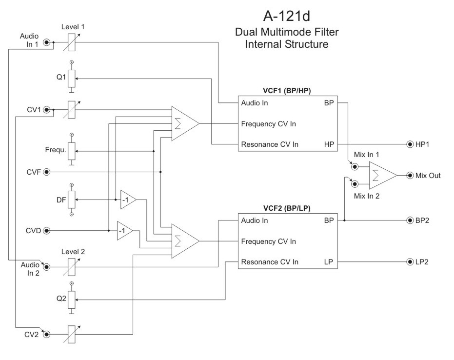
Breite/Width: 8 TE / 8 HP / 40.3 mm
Tiefe/Depth: 45 mm (gemessen ab der
Rückseite der Frontplatte / measured from the rear side of the front panel)
Strombedarf/Current: +30 mA (+12V) / -30 mA (-12V)
Standard Version : Euro 175.00
Vintage Edition : Euro 185.00
The price in US$ depends upon the exchange rate between Euro and US$ at the payment day.