A-152 Voltage Addressed Track&Hold / Analog Shift Register (ASR)/
Octal Switch (Multiplexer)

Patch tips with A-149-1 and A-152 from Navs: 
http://navsmodularlab.blogspot.com/2008/11/patch-of-day-random-multiplexer.html

click to enlarge


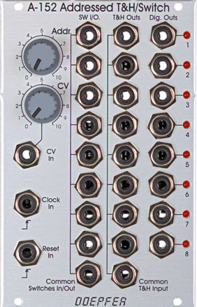
A-152 ist ein vielseitig einsetzbares Schalter/Multiplexer und Mehrfach-Track&Hold-Modul (T&H). Es vereint einen spannungsadressierbaren elektronischer 8-fach-Drehschalter ("Multiplexer") und eine 8-fache T&H, die auch als eine Art analoges Schieberegister verwendet werden kann. Der momentan aktive Ein/Ausgang wird mit einer LED angezeigt. Zusätzlich sind 8 digitale Ausgänge (high/low) verfügbar.

Statt der Adressierung des aktiven Ein/Ausgangs über eine Steuerspannung, ist auch die Clock/Reset-Steuerung des Moduls in der Art eines Sequenzers möglich. Die steigende Flanke des Clock-Signals löst dabei das Fortschalten zur nächsten Stufe aus. Ein "high"-Pegel am Reset-Eingang setzt auf Stufe 1 zurück.

Grundsätzliche Arbeitsweise des Moduls:  Die Summe der Spannungen des manuellen Adress-Regler "Addr." und der externen Steuerspannung "CV In", die mit dem Regler "CV" abgeschwächt werden kann bestimmen die aktive Stufe (1...8) der drei Untereinheiten Multiplexer, T&H und Digitalausgänge. Bei der Steuerung des Moduls über Clock/Reset muss die anliegende Steuerspannung konstant bleiben, da die Steuerspannung Priorität über die Clock/Reset-Steuerung hat (d.h. der CV-Abschwächer muss auf Null gedreht oder das an "CV In" angeschlossene Patch-Kabel abgezogen werden, und es darf nicht an dem Adress-Regler gedreht werden).
Die Untereinheit 1 ist ein  bidirektionaler 8-fach-Multiplexer (ein elektronischer 8-fach-Drehschalter). Bidirektional bedeutet, dass die Einheit in beide Richtungen - wie ein mechanischer Drehschalter - arbeitet. Der gemeinsame Anschluss (Common Switches In/Out) und die Einzelanschlüsse (SW I/O) können als Eingang oder Ausgang arbeiten. Werden die Einzelanschlüsse als Eingänge benutzt (z.B. mit den Ausgängen verschiedener Modulationsquellen wie etwa LFO, ADSR, Random usw. verbunden), so fungiert der gemeinsame Anschluss als Ausgang und umgekehrt. Es können sowohl Steuerspannungsquellen als auch Audiosignale geschaltet werden. Der schaltbare Spannungsbereich umfasst dabei den vollen A-100-Spannungsbereich von -12V....+12V, d.h. es können alle im A-100 vorkommenden Spannungen ohne Einschränkungen geschaltet werden.
Die Untereinheit 2 ist die adressierbare 8-fach-T&H. Die am gemeinsamen Eingang (Common T&H Input) anliegende Spannung wird auf den momentan angewählten Ausgang (einer der acht T&H Outs) durchgeschaltet. Sobald ein anderer Ausgang angewählt wird, wird an dem betreffenden Ausgang zuletzt anliegende Spannung gehalten (Track&Hold-Funktion). Es kann hiermit beispielsweise die "Toggling T&H"-Funktion des Buchla-Moduls 266 "Source of Uncertainty" realisiert werden, wobei hierfür jedoch nur die ersten beiden T&H-Ausgänge benötigt werden. Diese Einheit kann auch ähnlich einem
analogen (Schiebe)-register verwendet werden. Der Unterschied zu einem "echten" analogen Schieberegister besteht darin, dass die Analogspannungen nicht an den nächsten Ausgang weitergeschoben werden sondern dem betreffenden Ausgang fest zugeordnet bleiben. In einigen Anwendungsfällen ist das Resultat jedoch das gleiche (wenn man beispielsweise die Tonhöhen von 3 VCOs mit 3 Ausgängen des A-152 steuert).
Die Untereinheit 3 ist die Digitalausgang-Sektion. Der digitale Ausgang der momentan gewählten Stufe ist "high", alle anderen "low". Die Digitalausgänge können beispielsweise zur Triggerung von Hüllkurvengeneratoren oder zur Verringerung der anwählbaren Stufen im geclockten Modus verwendet werden, indem einer der Digitalausgänge mit dem Reset-Eingang verbunden wird.

Hinweis: Im Unterschied zur Sample&Hold-Schaltung (siehe S&H A-148) folgt bei T&H die Ausgangsspannung der Eingangsspannung, solange die T&H-Stufe (1...8) aktiviert ist. Erst beim deaktivieren der T&H-Stufe wird die letzte anliegende Spannung gehalten.

Hinweis: Das am Clock-Eingang angelegte Signal muss bezüglich des A-100-Systems, in dem sich der A-152 befindet, massebezogen sein. Der Grund hierfür ist eine Erkennungsschaltung am Clock-Eingang, mit der festgestellt wird, ob ein Clock-Signal zugeführt wird oder ob das Modul spannungsgesteuert arbeitet. Hierzu wird der Masse-Anschluss der Clock In-Buchse verwendet. Wird hier ein Clock-Signal von außen (d.h. nicht von einem Modul, das ebenfalls im A-100-Rahmen sitzt) zugeführt, fehlt der Massebezug und die Erkennungsschaltung am Clock-Eingang funktioniert nicht (d.h. der Clock-Eingang arbeitet nicht). Abhilfe schafft irgendein zweites Kabel zwischen den beiden System, da dann hierüber die Masseverbindung der beiden Systeme hergestellt wird.

Die deutsche Bedienungsanleitung ist als PDF-Datei auf unserer Website verfügbar: A152_Anl.pdf.

Technischer Hinweis: Um die elektronischen Schalter der Schalter-Einheit (linke Buchsenreihe) im Falle eines fehlerhaften Patches (z.B. Verbindung zweier Ausgänge) zu schützen, befindet sich ein 1k-Schutzwiderstand in jeder O/I-Leitung. Bei der Übertragung von CV-Spannungen für VCOs kann es daher zu sehr kleinen Spannungsabfällen kommen, die sich jedoch hörbar auf die Tonhöhe auswirken können. Daher sollten bei der Übertragung von CV-Signalen für VCOs Puffer zwischengeschaltet werden (z.B. A-180-3, A-180-4  oder der Precision Adder A-185-2). Der Einbau der Puffer in das Modul A-152 ist nicht möglich, da dann die Bidirektionalität nicht mehr gegeben ist.

Der gemeinsame T&H-Eingang kann mit Hilfe einer Steckbrücke auf den gemeinsamen Multiplexer-Anschluss normalisiert werden, d.h. sofern in die Buchse "Common T&H Input" kein Kabel eingesteckt wird, ist der Anschluss mit dem gemeinsamen Multiplexer-Anschluss "Common Switches In/Out" verbunden. Dies ermöglicht eine gemultiplexte T&H-Funktion, d.h. jedem der T&H-Ausgänge kann ein eigenes Signal für die T&H-Funktion zugeordnet werden.
Es ist auch möglich die T&H-Einheit dahingehend zu modifizieren, dass die Ausgänge S&H-Funktion statt T&H-Hold bekommen. Bei S&H (Sample&Hold) wird der momentan am gemeinsamen Eingang anliegende Spannungswert beim Adresswechsel sofort übernommen. Track&Hold ist ähnlich, jedoch folgt hier der Ausgang der Eingangsspannung, solange der betreffende Ausgang angewählt ist und übernimmt den Wert erst beim Wechsel auf eine andere Adresse. Die Modifikation ist auf der A-100 DIY-Seite beschrieben (nur in Englisch verfügbar).

Technischer Hinweis: Die T&H-Funktion wird rein analog mit Hilfe eines elektronischen Schalters gefolgt von einem Haltekondensator mit Pufferschaltung realisiert. Die Spannung am Ausgang driftet in der Haltephase, da sich der Kondensator allmählich über parasitäre Widerstände entlädt. Die Drift liegt bei typ. 200mV/Minute, hängt aber zusätzlich von mehreren Faktoren ab (z.B. Bauteile-Toleranzen, Luftfeuchtigkeit, Temperatur).  Für das Halten von CV-Signalen, die zur Tonhöhensteuerung von VCOs verwendet werden, ist das Modul daher nur bedingt geeignet (nur für kurze Zeiten).


click to enlarge


Module A152 is a very useful switching and T&H module. It combines a voltage addressed 1-to-8 multiplexer and 8 fold T&H that can be used as kind of an analog shift register too. The active in/output is displayed by a LED. The digital output of the currently addressed step outputs "high". The remaining digital outputs are low.
Instead of voltage control even clock/reset controlled addressing of the active step is possible. The rising edge of each clock signal causes an advance to the next state. The rising edge of the reset signal resets to step 1.

Basis principles: The sum of the voltages coming from the manual Address control and the CV input define the currently addressed step of the 3 sub-devices. If the module is controlled by clock and reset the control voltage has to remain unchanged as the CV control has priority over the clock/reset control (e.g. simply turn the CV control fully counterclockwise and do not touch the Address control knob).
Sub-device #1 is the bidirectional 8-fold multiplexer (kind of an electronical 8-fold rotary switch). Bidirectional means that it works into both directions like a mechanical rotary switch: the common socket may work as an output that is connected to one of the 8 inputs that are e.g. connected to modulation or audio sources. But the common socket may even function as input. In this case the signal applied to the common socket is output to the currently addressed single socket. The voltage range of the in/outputs to be switched is the full A-100 voltage range -12V....+12V. All A-100 signals can be switched without any restrictions.
Sub-device #2 is the addressed 8-fold T&H. The signal at the common T&H input is connected to the addressed T&H output. As soon as a new output is addressed the last voltage is stored at the output (Track&Hold function). The T&H section of the A-152 allows the emulation of the "toggling T&H" function of the Buchla module 266 "Source of Uncertainty". Only the first two T&H outputs of the A-152 are required for this application. This unit can be used also as kind of an
analog (shift) register. The difference to a "real" analog shift register is that the sampled output voltages are not shifted to the next output but remain allocated to the same output. But in some cases (e.g. controlling the pitch of 3 VCOs by 3 output voltages of the A-152) the result is the same.
Sub-device #3 is the digital output section. The digital output of the currently addressed turns to "high". All other digital outputs are low. The digital outputs can be used to trigger e.g. envelope generators or to control the reset input in the clocked mode to reduce the number of addressed stages.

Remark: In contrast to the Sample&Hold (see S&H A-148) the output voltage follows (i.e. tracks) to the input voltage as long as the corresponding stage (1...8) is active. Just when the stage is deselected the last voltage is held.

Remark: The clock signal that is fed into the Clock In socket has to be GND referenced to the A-100 frame. The reason for this is a recognition circuit at the clock input that is used to decide if the module is clock controlled or voltage controlled. For this recognition the GND pin of the Clock In socket is used. If an external clock signal is used (i.e. not coming from a module mounted into the A-100 frame where the A-152 is mounted) the GND reference is missing and the recognition circuit does not work (with the result that the clock input does not work). But there is a simple workaround: as soon as both systems are connected by means of any other patch cable that way the GND reference is established.

For more detailed information please look at the English user's manual: A152_man.pdf

Technical note: To protect the electronic switches in case of an unsuitable patch (e.g. connection of two outputs) a 1k protection resistor is inserted into the O/I line of each switch of the switching unit (left socket row). If control voltages used for VCOs are switched this may cause a small voltage drop and lead to undesired audible detuning. For this application we recommend to insert a CV buffer between A-150-8 and the VCO(s), e.g. A-180-3, A-180-4 or the Precision Adder A-185-2. Integrating the buffers into the module A-152 is not possible because this would ruin the bidirectionality of the switches.

The "Common T&H Input" socket can be normalled by jumpers to the "Common Switches In/Out" socket, i.e. the common T&H input is connected to the common switches In/out socket as long as no plug is inserted to the "Common T&H Input". This allows a multiplexed T&H, i.e. each T&H output has a separate signal to be sampled.
It is also possible to modify the T&H outputs for S&H function. If S&H (Sample&Hold) is chosen the voltage applied to the common input is sampled immediately when the output in question is adressed. T&H (Track&Hold) is similar but in this case the output follows the input as long as the output in question is addressed. The voltage is stored not until another output is selected. The modifiation is described on the A-100 DIY page.

Technical note: The T&H function is realized by pure analog circuitry (electronic switch followed by a holding capacitor and buffer). Consequently the output voltage drifts a bit in the holding state because the capacitor is discharged by parasitic resistors. The drift is about 200mV/minute but depends upon different conditions (e.g. humidity, temperature, tolerances of the electronic parts). For the storage of control voltages over a longer time used to control the pitch of a VCO the module is suitable to only a limited extent.


Breite/Width: 16 TE / 16 HP / 80.9 mm
Tiefe/Depth: 45 mm (gemessen ab der Rückseite der Frontplatte / measured from the rear side of the front panel)
Strombedarf/Current: +40mA (+12V) / -20mA (-12V)

Preis/price: Euro 160.00
The price in US$ depends upon the exchange rate between Euro and US$ at the payment day.
Anwendungsbeispiele / User examples

Graphischer VCO


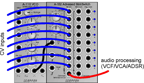
Die Abbildung zeigt das Grundprinzip eines sog. graphischen VCOs, d.h. eines VCOs dessen Kurvenform sich aus einer Abfolge bestimmter Spannungswerte zusammensetzt. Normalerweise werden diese Spannungen von vertikal angeordneten Schiebereglern erzeugt, so dass an Hand der Reglerpositionen die Kurvenform abgelesen werden kann. Im A-100 steht ein derartiger VCO bisher nicht zur Verfügung, da aus unserer Sicht der erforderliche Aufwand in keinem Verhältnis zu dem Resultat steht. Mit Hilfe des A-152 kann man einen graphischen VCO nachbilden, um sich ein Bild von der Funktion einer solchen Klangquelle zu machen. Und so funktioniert es:


Der CV-Adress-Steuereingang des A-152 wird von dem Ausgang eines VCOs (Sägezahn oder Dreieck) angesteuert. Man stellt den manuellen Adress-Regler und den CV-Abschwächer am A-152 so ein, dass gerade alle 8 LEDs aufleuchten. Dann ist sichergestellt, dass alle 8 Adressen am A-152 der Reihe nach durchschaltet werden, während der VCO seine Kurvenform "durchfährt" (daher ist ein VCO-Rechteck-Ausgang nicht geeignet). Der A-152 arbeitet so schnell, dass dies auch noch im moderaten Audio-Bereich klappt. Gibt man auf die Multiplexer-Eingänge 8 verschiedene Spannungen, so erhält man am gemeinsamen Multiplexer-Ausgang einen graphischen VCO, der die gleiche Frequenz wie der steuernde VCO besitzt.  Für die Erzeugung der 8 Spannungen gibt es verschiedene Möglichkeiten:


·       8 Festspannungen (z.B. von der CV Source A-176): Dies ist der "klassische" graphische VCO mit 8 von Hand einstellbaren Werten.

·       8 automatisch veränderliche Spannungen (z.B. 8 LFO-Ausgänge, z.B. von zwei A-143-3)

·       8 zufällige analoge Spannungen (z.B. Random Voltage von A-118 oder A-149-1, S&H-Ausgang A-148)

·       8 zufällige digitale Spannungen (z.B. A-149-2)

·       oder Kombinationen aus allen oben aufgeführten Vorschlägen

Bei den 3 letzten Beispielen ändert sich die Kurvenform mehr oder weniger zufällig. Bei Verwendung der analogen oder digitalen Zufallsspannungen von A-149-1 bzw. A-149-2 ergibt sich zusätzlich die Möglichkeit der getriggerten Veränderung, da bei diesen Modulen die neuen zufälligen Spannungen ja von einem Clock-Signal ausgelöst werden. Insbesondere mit einem A-155 Sequencer ergeben sich hier interessante Anwendungen, indem man beispielsweise die Trigger-Eingänge des A-149-1 mit dem Takt des Sequenzers oder von einer der Trigger-Reihen des A-155 steuert. Die Umschaltung auf die nächste zufällige Kurvenform kann dann synchron zu der Sequenz erfolgen.


Verwendet man den Dreieck-Ausgang des VCOs zur Ansteuerung des A-152, so besitzt das Ausgangssignal nur ungeradzahlige Harmonische, da ja die Kurvenform in beide Richtungen symmetrisch durchlaufen wird.

Graphic VCO


The picture shows the principle patch for a so-called graphic VCO. For a graphic VCO the waveform is determined by a sequence of voltage levels. Normally the levels are adjusted with faders and the fader positions represent the waveform. In the A-100 such a VCO is not available as we believe that the expenditure and costs do not correspond to the result. From our point of view the features of a graphic VCO are overestimated very often. But with the A-152 one has the tool to built a graphic VCO with a few additional modules only. And that's how it works:


The CV address input of the A-152 is connected to the output of a VCO (e.g. sawtooth or triangle output of an A-110 or A-111). The manual address control and the CV attenuator are adjusted so that just all 8 LEDs of the A-152 light up, i.e. that all 8 stages of the A-152 are addressed while the VCO passes through it's waveform (this is why only sawtooth/triangle/sine are suitable waveforms but not rectangle). The CV controlled address generator of the A-152 is able to work up to moderate audio frequencies. If different voltages are applied to the eight multiplexer inputs of the A-152 one obtains a graphic VCO signal at the common multiplexer output that has the same frequency as the VCO.

Here are some examples how to generate the eight voltages:


·       8 fixed voltages (e.g. from the CV source module A-176): This is the "classic" graphic VCO with manually adjustable values (for DIY's: 8 faders connected between GND and +12V could be used too)

·       8 automatically varying voltages (e.g. 8 LFO outputs from two A-143-3)

·       8 random analog voltages (e.g. random voltages from A-118 or A-149-1 or S&H A-148)

·       8 random digital voltages (e.g. A-149-2)

·       or any combination of the above suggestions


For the last 3 examples the waveform changes more or less accidentally. If the A-149-1 resp. A-149-2 is used the waveform changes can be synced as for these modules the random voltages are triggered by a clock signal. Especially in combination with an A-155 a lot of interesting applications may result. E.g. the clock inputs of the A-149-1 can be controlled by the sequencer clock or a A-155 trigger row. In both cases the change to the next waveform is in sync with the sequencer.


If the triangle output of a VCO is used to control the A-152 only odd harmonics will occur as the graphic waveform is passed through symmetrically in both directions.


Mono-Poly-Konverter / Analoges Schieberegister


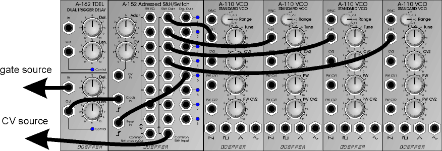
Die untenstehende Abbildung zeigt eine Anwendung des A-152, bei dem mit Hilfe der T&H-Einheit ein monophones Steuersignal (z.B. CV von einem Sequenzer, einem MIDI-CV-Interface oder einem monophonen Keyboard) in polyphone CV-Steuersignale umgewandelt und verschiedenen VCOs zugeführt wird. Und so funktioniert es:

Das Tonhöhen-Steuersignal wird dem gemeinsamen Eingang der T&H-Einheit zugeführt. Eine positive Flanke des zugehörigen Gate-Signal zeigt an, dass eine neue CV generiert wird. Es wird dazu verwendet die Adresse des A-152 weiterzuschalten. Das in die Gate-Leitung zwischengeschaltete Trigger-Delay A-162 ist wegen der zeitlichen Korrelation von CV-Änderung und positiver Gateflanke erforderlich. Die T&H-Einheit darf ja erst dann die CV-Steuerspannung übernehmen und speichern, wenn diese stabil anliegt. Wird hier zum falschen Zeitpunkt getriggert (z.B gerade dann, wenn sich der Ausgang auf eine neue CV einstellt), so entspricht das Ergebnis nicht der gewünschten Funktion. Man stellt zunächst die Trigger-Länge am A-162 so ein, dass der A-152 zuverlässig im gewünschten Tempo weiterschaltet (ist die Pulsbreite zu gering, so erkennt der A-152 u.U. das Triggersignal nicht oder schaltet unregelmäßig weiter). Dann stellt man den Delay-Wert am A-162 so ein, dass die CV-Werte wie gewünscht sequentiell auf die verschiedenen VCOs verteilt werden. In der Regel sind am A-162 Einstellungen knapp über dem Linksanschlag ausreichend.


In dem gezeigten Beispiel ist der Digitalausgang 5 auf den Reset-Eingang geführt, um die Zahl der verwendeten T&H-Ausgänge auf 4 zu beschränken.


Die Ausgänge der vier VCOs können vor der weiteren Signalbearbeitung (VCF, VCA, ADSR usw.) in einem Mixer A-138 gemischt, oder auch einzeln weiter verarbeitet werden. Im letzteren Fall können die Digitalausgänge des A-152 zur Triggerung der Hüllkurvengeneratoren dienen, die den VCOs zugeordnet sind.


Das Beispiel kann auf eine andere Anzahl von VCOs verlängert (max. 8) oder verkürzt werden. Hierzu muss nur der Reset-Eingang entsprechend beschaltet werden.


Ein Sonderfall ist die Beschränkung auf 2 Ausgänge. Dann entspricht die Funktion annähernd dem der S&H-Einheit in dem Buchla-Modul 266 Source of Uncertainty. Der Unterschied besteht nur darin, dass eine T&H statt einer S&H zum Einsatz kommt (siehe hierzu Seite 2). Falls genau dies benötigt wird, könnte man eine "echte" S&H A-148 zwischenschalten.


Der A-152 kann auch dahingehend modifiziert werden, dass die T&H-Einheit als S&H-Einheit arbeitet. Details hierzu finden Sie auf der DIY-Seite zum A-100 auf unserer Web Site www.doepfer.de.

Mono-Poly-Konverter / analog shift register


The picture shows an application of the A-152 that distributes a monophonic pitch control voltage (e.g. the CV of a sequencer,  a MIDI-to-CV interface or a monophonic keyboard) into several polyphonic control voltages that are used to control several VCOs. And that's how it works:


The pitch CV is connected to the common input of the T&H unit. The positive transition of the corresponding gate signal indicates that a new CV is generated (e.g. by pressing a key on the keyboard or during the advance to the next sequencer step). The gate signal is used to trigger the advance to the next address of the A-152. The trigger delay connected between the gate source and the clock input of the A-152 is required because of the timing between the positive transition of the gate signal and the CV change. The T&H has to take over and store the CV not before the CV is stable. Otherwise the result will not meet the expectations. As the time correlation between the gate transition and the CV change may vary the A-162 is used to solve problems that may arise from this. Ideally the gate transition and CV change happens exactly simultaneously, but "simul-taneously" is a problem in the real world as there are always some delays in the micro/millisecond range that may cause problems (e.g. the MIDI-to-CV interface or sequencer of manufacturer #1 generates the gate transition 200us before the CV change but for manufacturer #2 the behaviour is reverse and the delay is 500 us). To avoid such problems the A-162 is used. First the trigger length is adjusted so that the A-152 triggers correctly. If the width is too short the A-152 may not trigger or the step advances are uneven. After that the delay time is adjusted so that the CV values appear sequentially at the T&H outputs of the A-152 as expected. Usually the A-162 settings will be close to the left-most positions of the controls for delay and length.


In the example the digital output five is connected to the reset input of the A-152 to limit the number of outputs to four.

The four VCO outputs can be mixed in an A-138 before the subsequent signal processing (VCF,VCA,ADSR  ...). But even each VCO outputs can be processed separately. In this case the digital outputs of the A-152 may be used to trigger the envelope generators that are assigned to the corresponding VCO.


The number of outputs can be decreased or increased by connecting the reset input to another digital output.


A special case is the limitation to two outputs. This leads to the function of the toggling S&H unit of the Buchla module 266 Source of Uncertainty. The only difference is that the Buchla module contains two S&H instead of two T&H. If an A-148 S&H is connected between the CV source and the A-152 the functions are identically.


Another solution is to modify the A-152 so that the T&H section works as S&H. For details please refer to the DIY page on our web site www.doepfer.com.


7-faches Ribbon-Gate


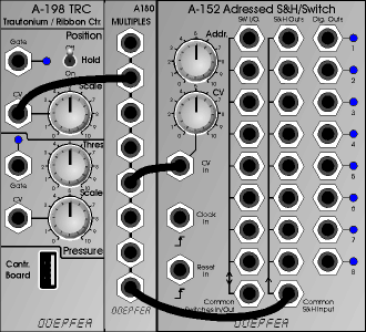
Die Abbildung zeigt eine Anwendung des A-152 in Kombination mit dem Ribbon-Controller A-198. Die Positions-Ausgangsspannung des A-198 steuert hierbei die Adresse des A-152. Bei korrekter Einstellung des manuellen Adress-Reglers und des CV-Abschwächers am A-152 überstreicht der Positionssensor des A-198 den gesamten Adressbereich des A-152 und es wird jeweils ein kleiner Positionsbereich des A-198 einer der acht Adressen des A-152 zugeordnet. Bringt man den Hold-Schalter am A-198 in die Position "Off", so springt der A-152 beim Wegnehmen des Fingers auf Adresse 1. Sobald man den Positionssensor des A-198 berührt, wird am A-152 die Adresse 2 ... 8 angewählt und der betreffende Digitalausgang geht auf "high" - angezeigt von der betreffenden LED. Hiermit kann ein 7-facher manueller Gate-Generator realisiert werden, der in der Art eines Schlagzeuges bedient wird: je nach Position des Fingers wird ein anderer Gate-Ausgang aktiviert. Die Gate-Ausgänge können beispielsweise zur Triggerung von elektronischen Schlaginstrumenten verwendet werden, die mit A-100-Modulen nachgebildet wurden. Auch das Triggern des Sampler-Moduls A-112 ist denkbar. Grundsätzlich können die Gate-Ausgänge für jede Art von Gate/Trigger/Clock-Aufgaben im A-100 verwendet werden.

Zusätzlich wurde in dem Beispiel die Positions-CV auch auf den gemeinsamen T&H-Eingang gepatcht. Man hat an den T&H-Ausgängen Steuerspannungen zur Verfügung, die aber jeweils nur in einem bestimmten Bereich der Positions-CV des A-198 folgen und zwischengespeichert werden, sobald der Finger den betreffenden Bereich verlässt ("analoge Split-Zonen").

Der Multiplexer-Bereich kann zusätzlich dazu verwendet werden, bestimmte Funktionen zu schalten (z.B. um unterschiedliche Modulations- oder Audioquellen auf ein Modul zu legen).

7-fold Manual Ribbon Gate


The picture shows an application of the A-152 in combination with the ribbon controller A-198. The position control voltage of the A-198 is used to address the A-152. If the manual address control and the CV attenuator are adjusted in the right way the position sensor of the A-198 covers the complete address range of the A-152 and a small share of the position range is assigned to one of the eight addresses of the A-152.

If the hold switch of the A-198 is set "off" the A-152 jumps to address 1 as soon as the finger is removed from the position sensor. As soon as the sensor is touched, one of the stages in the range 2...8 is addressed and the corresponding digital output turns to "high" - displayed by the corresponding LED. This leads to a 7-fold manual gate generator that can be operated like a percussion set. According to the position of the finger, that touches the position sensor of the A-198 one of the gate outputs of the A-152 is active. The gate outputs may be used to trigger percussive sounds stored in an  A-112 sampler module or percussive patches based on other A-100 modules.


In principle the gate outputs can be used for any gate/trigger/clock function in the A-100.


In the example the position CV is also patched to the common T&H input. At the T&H outputs control voltages are available that follow the position CV of the A-198 in a certain range. As soon as the finger leaves the corresponding range the last voltage is stored.


The multiplexer unit can be used for additional switching functions (e.g. to connect different modulation or audio sources to a module).