A-111-5 Synthesizer
Voice
Wiederauflage
Herbst 2020 / Reissue Fall 2020
 |
 |
|
Standard Edition A-111-5 |
Vintage Edition A-111-5V |
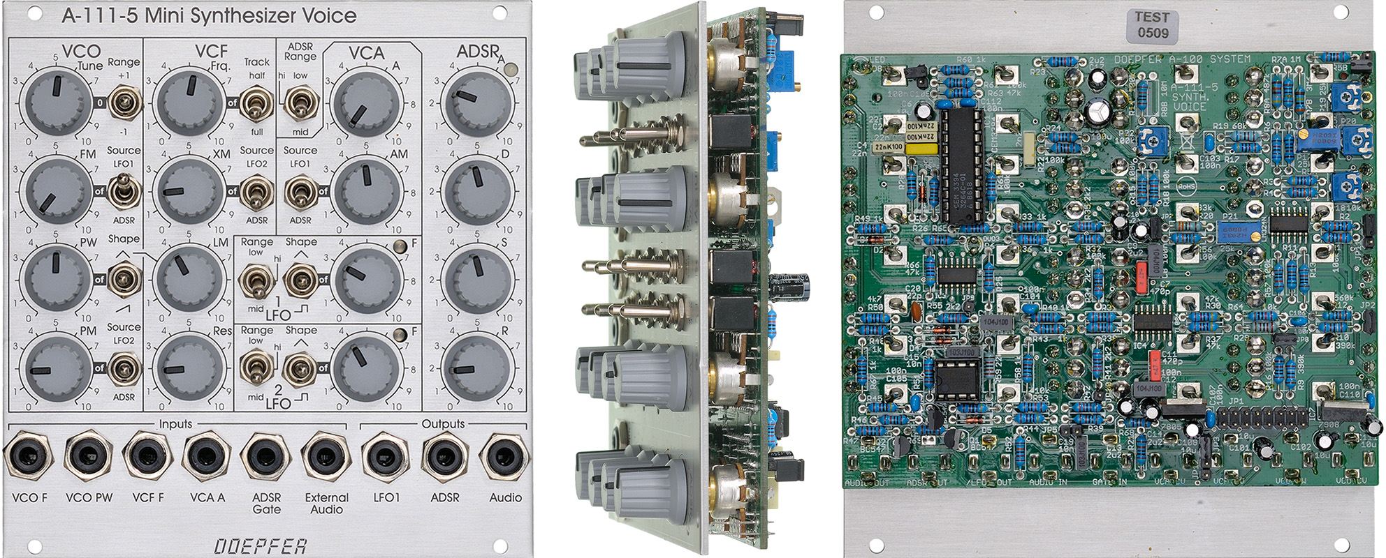
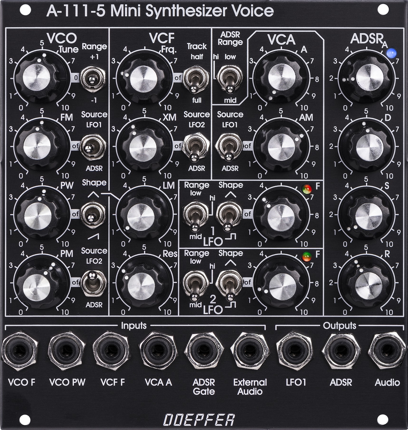
VCO
- manual tune control (with an internal jumper the range can be set to ~ +/-1 half an octave or ~ +/-2.5 octaves)
- range switch -1 / 0 / +1 octave
- frequency range about 30Hz ... 10kHz
- FM (frequency modulation) control with modulation source switch (LFO1 / off / ADSR)
- manual pulsewidth control for rectangle waveform
- PWM control with modulation source switch (LFO2 / off / ADSR)
- waveform switch (sawtooth / off / triangle)
- the sum of the waveform chosen by this switch and the rectangle is fed into the VCF (to turn the rectangle off the PW control has to be set fully CCW)
- external CV input for VCO frequency (1V/octave)
- external CV input for external PWM of the rectangle
- internal CV input for frequency (1V/octave) connected to the A-100 bus via jumper, the jumper can be used to interrupt this internal connection if not wanted
VCF
- 24 dB low pass
- ~ 12 octaves frequency range
- manual frequency control
- tracking switch half - off - full (internally connected to the external frequency CV input of the VCO, i.e. the VCF tracks to the VCO if the switch is set to "half" or "full" position)
- XM: exponential FM (frequency modulation) control with modulation source switch (LFO2 / off / ADSR)
- LM: linear FM (frequency modulation) control to modulate the VCF by the triangle of the VCO in a linear (!) manner
- manual resonance control (up to self oscillation)
- external audio input (this signal is added to the VCO signal, the level should not exceed 1Vpp, otherwise clipping/distortion may occur, if necessary an attenuator has to be used, e.g. A-183-1)
- external CV input for filter frequency
- 1V/octave tracking for usage of the VCF as a sine wave oscillator (not as precise as the VCO but much better than most of the other filters)
VCA
- manual amplitude control
- AM (amplitude modulation) control with modulation source switch (LFO1 / off / ADSR)
- external CV input for VCA amplitude
- special control scale: exponential scale in
the range from about -20dB to -80/90dB, linear scale from about -20dB to 0dB
Remark: this special control scale results in a loudness behaviour that is a bit different from pure linear or exponential VCAs
LFO1 and LFO2
- manual frequency control
- waveform switch (triangle / off / rectangle)
- range switch (low, audio, medium)
- LED display (dual green/red color for positive/negative share of the signal)
- the inverted LFO1 signal is available as an additional socket (to use the LFO1 signal for external modules)
- an internal jumper can be used to select between the LFO1 signal or the inverted LFO1 signal
ADSR
- manual controls for Attack, Decay, Sustain, Release
- range switch (long, short, medium)
- blue LED display
- ADSR signal is available as an additional socket (to use the ADSR signal for external modules)
- Gate input connected to the A-100 bus via jumper, the jumper can be used to interrupt this internal connection if not wanted
Remarks:
- As the LFO frequencies can go up to moderate audio range (~ 5kHz) even audio FM effects of VCO (pitch and pulsewidth), VCF and ADSR are possible !
- If the VCO is turned off (waveform switch = center position, pulsewidth control = fully CCW) and the VCF resonance is set to maximum the module can be used as a sine oscillator. The sine can be modulated in a linear manner from the triangle wave of the VCO and by LFO2 in an exponential manner at the same time !
- from the factory the socket labelled "LFO1" outputs the inverted LFO1 signal. But as the module has several internal pin headers available even another signal may appear at this socket by changing the internal module patch. These six pin headers are available: LFO1 output, LFO2 output, ADSR output, inverter input, inverter output, output socket. The internal default patch is LFO1 -> inverter input, inverter output -> output socket (i.e. socket = inverted LFO1). But even another signal can be patched to this socket (e.g. inverted ADSR, non-inverted LFO1, inverted or non-inverted LFO2). It is also possible to add a blind panel next to the A-111-5 with a couple of sockets that are connected to the corresponding pins of the A-111-5 pc board. The in- and outputs of the VCO, VCF and VCA are not available as pin headers because the VCO, VCF and VCA are internally connected in the circuit which is used in this module.
A more detailed description of the module can be found in the user's manual A111_5_man.pdf
Pay attention that the orientation of the bus connection cable of the A-111-5 is different compared to all other A-100 modules: A111_5_orientation_bus_cable.pdf
As the special circuit
CEM3394
used in this module is no longer available the module had to be discontinued.
Wiederauflage Herbst 2020 mit AS3394 / Reissue Fall 2020 with AS3394
A-111-5 Sketch
This is nothing exceptional. Just the standard VCO/VCF/VCA synthesizer patch. These operations carried out during the example:
- default setting: VCO waveform = sawtooth + rectangle, VCF frequency = maximum, VCF resonance = minimum, VCF modulation = minimum, ADSR times at medium settings
- VCO tuned manually from maximum to about position 2
- filter frequency lowered
- ADSR times manually reduced
- VCF frequency, VCF modulation depth and VCF resonance altered manually (modulation source = ADSR)
- PWM added (about at the center of the example, leads to a richer sound), modulation source = triangle LFO 1
- VCO octave switch operated (center/up/center/down/center)
- VCO tune changed
This example shows some FM sounds that can be generated by the A-111-5. Only the self-oscillation VCF is used as sound source. The VCO is not heard but only used for linear FM (LM).
- default setting: VCO = off, VCF resonance = maximum, no VCF FM or LM, ADSR times at medium settings
- ADSR times manually reduced
- Linear FM (LM) control from zero to about middle position and back to zero
- Exponential FM (XM) control from zero to about middle position and back to zero, modulation source = LFO2 triangle in audio range
- Linear and exponential FM (LM and XM) controls both from zero to about middle position
- small VCO modulation added, modulations source = ADSR
- Linear and exponential FM (LM and XM) controls both back to zero
Tiefe/Depth: 40 mm (gemessen ab der Rückseite der Frontplatte / measured from the rear side of the front panel)
Strombedarf/Current: +80mA (+12V) / -50mA (-12V)
Standard Version : Euro 325.00
Vintage Edition : Euro 375.00
The price in US$ depends upon the exchange rate between Euro and US$ at the payment day.
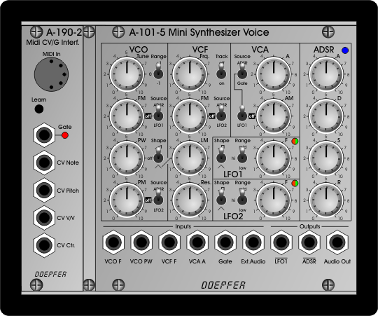 |
Miniature Synthesizer
based on A-111-5 and Midi-Interface A-190-3
built into a A-100 miniature case |
 |
|
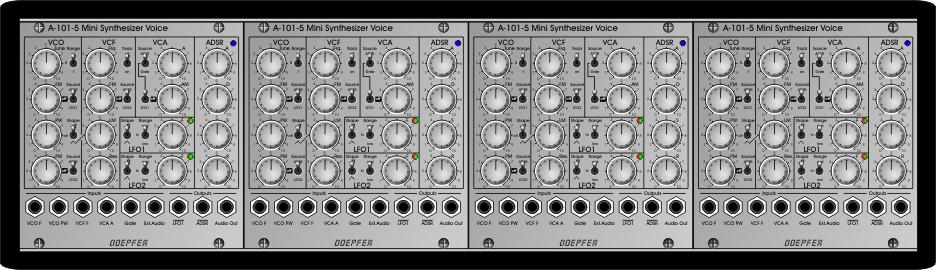
| Four voice polyphonic synthesizer
based on four A-111-5. The voices can be controlled e.g. by the polyphonic Midi interface A-190-5. |