A-135-2 Quad VCA / Voltage Controlled Mixer
|
click to enlarge |
click to enlarge |
 |
 |
|
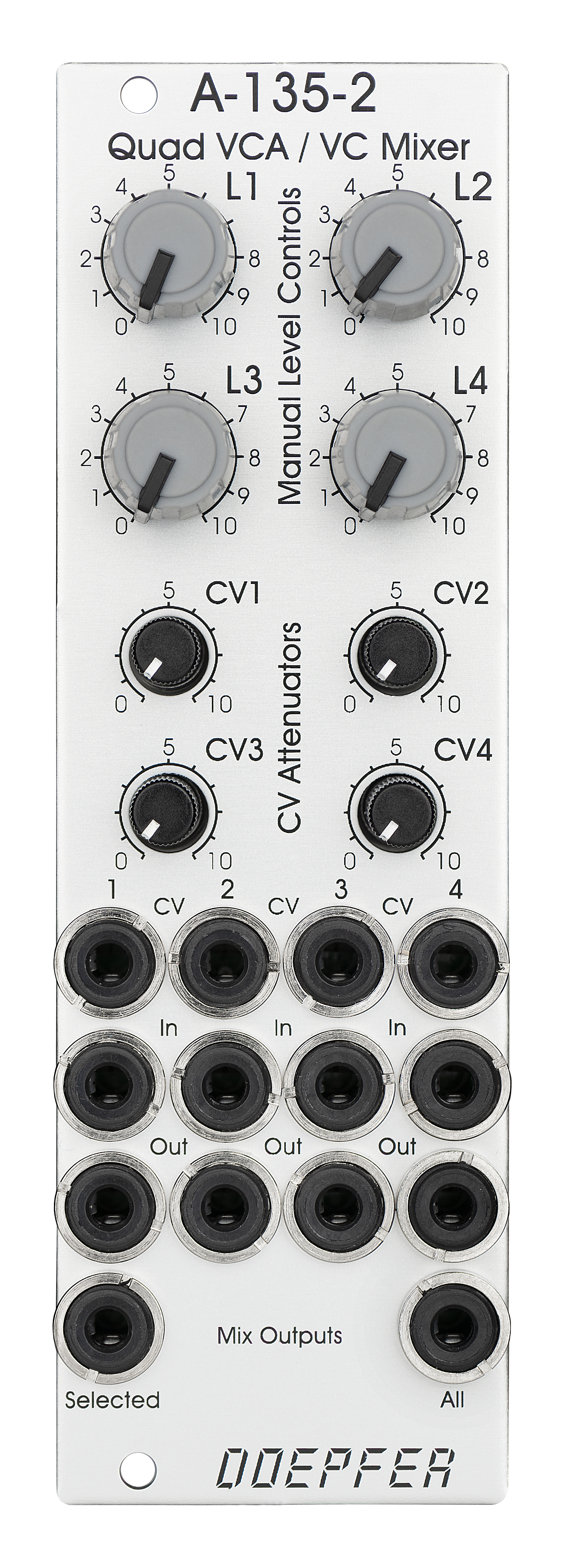
Standard Edition |
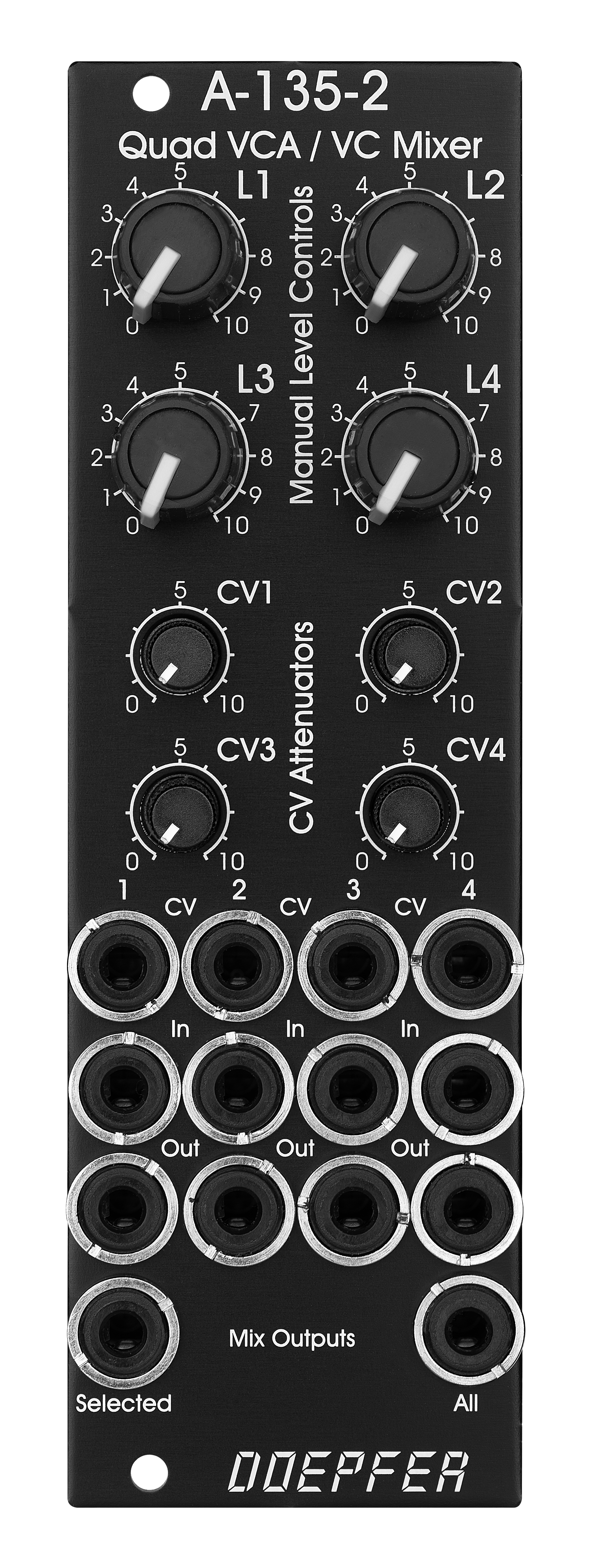
Vintage Edition |
Bedienelemente, Ein/Ausgänge und Funktionen jedes der vier VCAs:
-
Pegel (manuelle Einstellung der VCA-Verstärkung), mit kleinem gummiertem Drehknopf (L1...L4)
-
Steuereingang mit zugehörigem Abschwächer (CV1...CV4), für den vollen VCA Steuerbereich werden ca. 0...+5V Steuerspannung benötigt (Abschwächer voll aufgedreht), höhere Steuerspannungen können mit den Abschwächern angepasst werden. Die Abschwächer sind ohne Drehknopf und besitzen nur eine Kunststoffachse mit Markierungsstrich
-
Signal-Eingang
-
Signal-Ausgang
-
Ein- und Ausgänge sind gleichspannungsgekoppelt. Daher kann das Modul auch zur Bearbeitung von Audio- oder Steuersignalen verwendet werden (z.B. um steuerbare Amplituden von LFOs oder Hüllkurven zu erhalten).
-
Die Signal-Eingänge besitzen keine Abschwächer, das Modul kann aber Signale bis ca. 15Vss (d.h. von ca. -7.5V bis ca. + 7.5V) verzerrungsfrei verarbeiten. Für Signale mit einem höheren Pegel müsste ein externer Abschwächer vorgeschaltet werden (z.B. A-183-1).
-
Der verfügbare Verstärkungsbereich beträgt 0...1 (die maximale Verstärkung "clippt" bei 1, d.h. auch bei weiterer Erhöhung der Steuerspannung bleibt die Verstärkung auf dem Wert 1)
Funktionen des spannungsgesteuerten Mixers:
-
zwei Ausgänge ("Selected" und "All")
-
Selected Ausgang: hier erscheint das Summensignal aller VCAs, sofern in die Out-Buchse des betreffenden VCAs kein Patchkabel eingesteckt ist. VCAs, bei denen in die Out-Buchse ein Patch-Kabel eingesteckt wird, werden aus der Summe entfernt
-
All-Ausgang: hier erscheint das Summensignal aller VCAs, unabhängig davon Patchkabel in die Out-Buchsen eingesteckt sind.
-
Die maximale Verstärkung in den Mix-Ausgängen liegt bei ca. 0.6, um Clipping in den Summensignalen zu vermeiden.
Spezielle Betriebsarten des spannungsgesteuerte Mixers (durch Aufstecken / Entfernen von internen Steckbrücken wählbar)
-
Dualer Stereo-VCA: In diesem Fall wirkt die Steuereinheit von VCA1 (L1 + CV1) auch auf VCA3 und die Steuereinheit von VCA2 (L2 + CV2) auch auf VCA4. Die Steuereinheiten von VCA3 (L3 + CV3) und VCA4 (L4 +CV4) sind ohne Funktion
-
Vierfach-VCA: In diesem Fall wirkt die Steuereinheit von VCA1 (L1 + CV1) auf alle vier VCAs. Die Steuereinheiten von VCA2 (L2 und CV2), VCA3 (L3 + CV3) und VCA4 (L4 +CV4) sind ohne Funktion. In dieser Betriebsart hat das Modul die gleiche Funktion wie A-132-2. Das Modul A-132-2 wird daher abgekündigt.
-
Normalisierung der Signal-Eingänge: Über interne Steckbrücken kann der Signal Eingang 1 auf Signal Eingang 2, Signal Eingang 2 auf Signal Eingang 3 und Signal Eingang 3 auf Signal Eingang 4 normalisiert werden. Somit kann ein Signal auf 4 verschiedene Kanäle per Spannungssteuerung verteilt werden (z.B. für quadrophonische Verteilung von Audio-Signalen). Als Steuerquellen können hierfür z.B. die Module A-144 (Morphing Controller) oder A-143-9 (Quadratur-LFO) verwendet werden.
-
Ab Werk sind die Normalisierungen der Signaleingänge nicht aktiviert. Falls dies gewünscht ist, müssen die betreffenden Steckbrücken eingesetzt werden.
Zusätzliche technische Daten für jeden VCA (basierend auf den Spezifikationen der verwendeten VCA-Bausteine CEM3360/AS3360):
-
Übersprechen zwischen zwei VCAs: typ. - 80dB
-
Signalabschwächung bei 0V CV: typ. -70dB
-
Klirrfaktor: typ. 1%
-
Steuerspannungsdurchgriff: 15mV
Das folgende Dokument zeigt die Positionen und Funktionen der Steckbrücken des Moduls: A135_2_jumpers.pdf
A-135-2 is a miniature version of the A-135-1. Behind a front panel with 8 HP only four linear VCAs (voltage controlled amplifiers) and a voltage controlled mixer based on the VCAs are available.
Controls, In/Outputs and Functions of each VCA:
-
Level (manual control of the VCA amplification), small rubberized knob (L1...L4)
-
Control voltage input with associated attenuator (CV1...CV4), for the full VCA control range about 0...+5V control voltage are required (attenuator fully clockwise), for higher control voltages the attenuator is used, the attenuators are without knobs, just plastic shafts with white marker
-
Signal Input
-
Signal Output
-
All inputs and outputs are DC coupled. Consequently the VCAs can be used to process both audio and control voltages (e.g. to control the level of LFOs or envelopes)
-
The signal input is not equipped with an attenuator. But the VCAs can process all signals up to 15Vpp / -7.5...+7.5V without clipping. In case of higher levels an external attenuator is required (e.g. A-183-1).
-
The available amplification range is 0...1, the maximal amplification is 1 (i.e. it "clips" and remains at 1 even if the control voltage goes beyond the value that corresponds to amplification 1)
Functions of the voltage controlled mixers:
-
two outputs ("Selected" and "All")
-
Selected output: the ouput if a VCA is removed from this sum signal when a plug is inserted into the corresponding VCA output.
-
All output: sum of all VCA outputs, regardless of inserted plugs into the VCA outputs
-
The maximal amplification is about 0.6 to avoid clipping at the mixer outputs (otherwise the outputs may distort with 15Vpp signals at each signal input and full amplifications)
Special functions of the voltage controlled mixer (selectable by internal jumpers)
-
Dual Stereo VCA: In this case the control unit of VCA1 (L1 + CV1) affects also VCA3 and the control unit of VCA2 (L2 + CV2) affects also VCA4. The control units of VCA3 (L3 + CV3) and VCA4 (L4 +CV4) are out of operation.
-
Quad VCA: In this case the control unit of VCA1 (L1 + CV1) affects all four VCAs. The control units of VCA2, VCA3 and VCA4 are out of operation. In this mode the module has the same function as module A-132-2. That's why module A-132-2 will be discontinued.
-
Normalling of the signal inputs: by means of internal jumpers signal input 1 can be normalled to signal input 2, signal input 2 to signal input 3 and signal input 3 to signal input In 4. That way the same input signal can be distributed to four different channels by means of control voltages (e.g. quadrophonic distribution of audio signals). Suitable control voltage sources are e.g. A-144 (Morphing Controller) or A-143-9 (Quadrature LFO).
-
In the factory the normalling jumpers for the signal inputs are not installed. To enable the normallings the corresponding jumpers have to be installed.
Additional technical specification for each VCA (based on the specifications of the VCA circuits CEM3360/AS3360 used in the module):
-
Crosstalk between VCAs: typ. - 80dB
-
Signal attenuation at 0V CV: typ. -70dB
-
Total harmonic distortion: typ. 1%
-
Control voltage feedthrough: max. 15mV
The following document shows the positions and functions of the jumpers of the module: A135_2_jumpers.pdf
Breite/Width: 8 TE / 8 HP / 40.3 mm
Tiefe/Depth: 45 mm (gemessen ab der Rückseite der Frontplatte / measured
from the rear side of the front panel)
Strombedarf/Current: +40mA (+12V) / -40mA
(-12V)
Standard Version : Euro 150.00
Vintage Edition : Euro 160.00
The price in US$ depends upon the exchange rate between Euro and US$ at the payment day.