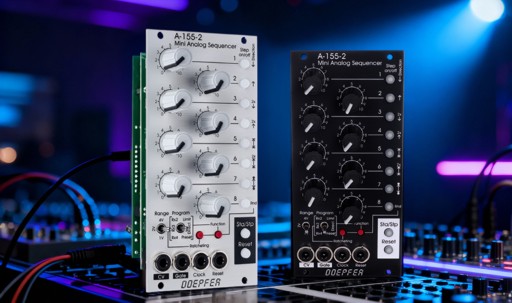
A-155-2 Miniature Analog Sequencer
https://www.amazona.de/test-doepfer-a-155-2-mini-analog-sequencer-eurorack
https://www.youtube.com/watch?v=XyPDmC0Q1zg&feature=youtu.be
|
click to enlarge |
 |
 |
Das Modul A-155-2 ist ein kleiner, sehr kompakt aufgebauter Analog-Sequencer mit vielen Funktionen. Die Sequenz hat eine Länge von 8 Stufen. Für jede Stufe steht neben dem Drehregler für die Einstellung der Steuerspannung ein beleuchteter Taster zur Verfügung, der eine Reihe von Funktionen übernimmt: im Normalbetrieb wird mit dem Taster das Gate-Signal an der betreffenden Stufe gesetzt (Taster leuchtet) oder gelöscht (Taster leuchtet nicht). In Verbindung mit den Bedienelementen am unteren Rand haben die beleuchteten Taster aber weitere Funktionen: wird der Taster Function gedrückt gehalten, so kann - je nach Stellung des rechten Program-Schalters - mit den Leuchttastern die Funktion Sequenzlänge (Schalter in Position Limit), Laufrichtung (Schalter in Position Direct. = Direction) oder Preset-Verwaltung (Schalter in Position Preset) angewählt werden. Wird der Taster Ratcheting gedrückt gehalten, so kann - je nach Stellung des linken Program-Schalter mit den Leuchttastern ein 2-, 3- oder 4-faches Ratcheting für jede Stufe getrennt an- und abgeschaltet werden (Schalter in Position Rx2, Rx3 oder Rx4).
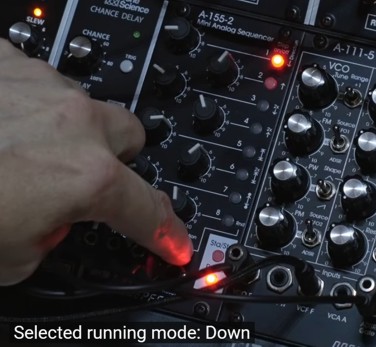
Ist die Funktion Direct. angewählt, so kann eine der folgenden Laufrichtungen mit den beleuchteten Tastern gewählt werden:
-
Abwärts
-
Aufwärts
-
2 x Abwärts (jede Stufe wird im normalen Tempo zweifach gespielt, nicht zu verwechseln mit Ratcheting x2, siehe unten)
-
2 x Aufwärts (jede Stufe wird im normalen Tempo zweifach gespielt, nicht zu verwechseln mit Ratcheting x2, siehe unten)
-
Pendeln Typ 1 (Anfangs- und End-Stufe werden doppelt gespielt)
-
2 x Pendeln Typ 1 (jede Stufe wird zweifach, Anfangs- und End-Stufe vierfach gespielt)
-
Pendeln Typ 2 (Anfangs- und End-Stufe werden einfach gespielt)
-
Zufällig (Rnd)
Ist die Funktion Limit angewählt, so kann
mit den beleuchteten Tastern die Länge der Sequenz begrenzt werden. Dabei
werden erste und letzte Stufe der Sequenz mit 2 Tastern angewählt.
Ist die Funktion Preset angewählt, so kann mit den beleuchteten Tastern
eines der 8 Presets abgerufen werden. In einem Preset werden die Parameter
gesetzte Stufen, Sequenzlänge und Ratcheting gespeichert. Die
Positionen der 8 Regler werden nicht in den Presets gespeichert, sondern nur die
zuvor erwähnten Lauf-Parameter !
Wird der Taster Ratcheting gedrückt gehalten, so kann
- je nach Stellung des linken Program-Schalter mit den Leuchttastern 2-,
3- oder 4-faches Ratcheting für jede Stufe getrennt an- und abgeschaltet werden
(Schalter in Position Rx2, Rx3 oder Rx4). Ist an der
betreffenden Stufe bereits ein anderes Ratcheting angewählt, so wird dieses
dabei überschrieben. Näheres zu der Ratcheting-Funktion ist bei dem Modul A-160-5
erklärt.
Mit den Tastern Start/Stop und Reset wird die Sequenz von Hand
gestartet, gestoppt oder auf Anfang gesetzt. Für die Reset-Funktion steht auch
ein externer Steuereingang Reset zur Verfügung.
Das Modul hat keinen eingebauten Clock-Generator. Das Tempo wird über dem Clock-Eingang
von außen gesteuert, wobei die positive Flanke des eingehenden Clock-Signals
den Sprung auf die nächste Stufe der Sequenz auslöst.
Der Spannungsbereich der vom Modul erzeugten Steuerspannung kann in 3 Bereichen
mit dem Kippschalter Range umgeschaltet werden: 0...+1V / 0...+2V / 0...+4V.
Die
Steuerspannung wird an der Buchse CV ausgegeben. Die Spannung ist nicht
quantisiert. Intern steht eine 2-polige Stiftleiste zur Verfügung, an der die
Daten in Form von Midi-Signalen zur Verfügung stehen (Note On/Off ab
Midi-Tonhöhe 36 auf Midi-Kanal 1). Hier kann intern ein Midi-CV-Interface
angesteuert werden, falls quantisierte Steuerspannungen gewünscht sind, z.B.
das Micro-CV-Interface A-190-9. Falls die Daten
des A-155-2 in Form eines Midi-Signals benötigt werden, kann das geplante
universelle Midi-Ein/Ausgangs-Modul A-180-8 verwendet werden.
Das Gate-Signal erscheint an der Buchse Gate. Die Pulsbreite des
Gate-Signals wird dabei von der Pulsbreite des Clock-Signals bestimmt, sofern an
der betreffenden Position kein Ratcheting angewählt ist.
Bedienungs- und Anzeige-Elemente:
-
1...8 (Drehregler): manuelle Einstellung der Spannung für jede Stufe
-
1...8 (beleuchtete Taster): manuelle Gate-Aktivierung für jede Stufe, zusätzlich auch für Sonderfunktionen verwendet (Einstellungen von erster/letzter Stufe, Laufrichtung und Ratcheting) in Kombination mit anderen Bedienelementen
-
Range: Kippschalter zur Einstellung des Steuerspannungsumfangs
-
Program: Kippschalter zur Anwahl einer Funktion in Verbindung mit dem Tastern Ratcheting und Function
-
Ratcheting: Taster zur Programmierung des Ratchetings in Verbindung mit dem Kippschalter Program
-
Function: Taster zur Programmierung des Sequenzlänge (Limit) und Laufrichtung (Direct.), sowie der Preset-Verwaltung (Preset)
-
Sta/Stp : Taster zur manuellen Steuerung von Start und Stop, im laufenden Betrieb zeigt die LED dieses Taster den Zustand des Gate-Signals an (d.h. sie blinkt im Rhythmus des Gate-Ausgangs)
-
Reset : manueller Reset-Taster
-
CV : Steuerspannung-Ausgang
-
Gate : Gate-Ausgang
-
Clock: Clock-Eingang, die Pulsbreite des Clock-Signals bestimmt auch die Pulsbreite des ausgegebenen Gate-Signals
-
Reset: Reset-Steuereingang, Art der Ausführung über interne Jumper wählbar (z.B. positive Flanke erzeugt Sprung auf erste Stufe / positiver Pegel erzeugt Sprung auf erste Stufe und verharrt auf dieser Stufe solange der Reset-Eingang auf high liegt / Warten auf nächste positive Clock-Flanke vor Reset-Ausführung / ...)
Technische Details:
- Gate Ausgangsspannung: ca. 0V/+10V
- erforderlicher Clock Eingangspegel: min. +3V
- erforderlicher Reset Eingangspegel: min. +3V
- maximale Clock-Frequenz: > 10kHz (z.B. für Graphic-VCO-Anwendung)
- interner Midi-Ausgang: Midi-Kanal 1, Midi-Noten-Werte 36-48, 36-60 oder 36-84 je nach Stellung des Range-Schalters
Die Bedienungsanleitung ist als pdf-Datei auf unserer Website verfügbar: A-155-2_Anleitung.pdf
Das Modul wird auch in einer 1U-Version unter der Modulnummer A-155-3 produziert.
Module A-155-2 is a small, very compact designed analog sequencer with a lot of features. The sequence length is 8 steps. Each step has available a control for the adjustment of the control voltage for this step and an illuminated momentary switch (button). The buttons are used in the standard running mode to turn on/off the gate of the step in question (button illuminated = gate on, not illuminated = gate off). In combination with other controls at the bottom of the front panel the buttons are used for additional functions: depending on the position of the Program toggle switch the button Function is used to program the length of the sequence (switch position Limit), the running direction (switch position Direct.) or to call up the preset management (switch position Preset) .
When function Direct. (Direction) is selected these running modes are available:
-
Down
-
Up
-
2 x Down (each step is played twice with the normal tempo, not to be confused with Ratcheting x2, see below)
-
2 x Up (each step is played twice with the normal tempo, not to be confused with Ratcheting x2, see below)
-
Pendulum type 1 (start and end step are played twice)
-
2 x Pendulum type 1 (each step is played twice with the normal tempo, start and end step are played 4x)
-
Pendulum type 2 (start and end step are played once)
-
Random (Rnd)
When function Preset is selected the illuminated buttons are used to call up one of the 8 presets. In each preset these parameters are stored: active steps, length of the sequence, ratcheting. The positions of the 8 controls are not stored in a preset but only the running parameters !
Depending on the position of the Program
toggle switch the Ratcheting button is used to program the ratcheting
feature (x2, x3, x4) individually for each step of the sequence (toggle switch Program
in position Rx2, Rx3 or Rx4). In case that at the step in
question another ratcheting is already programmed (e.g. x2 or x3 when x4 is
chosen) the other ratcheting is overwritten (kind of radio button function
between the ratchetings x2, x3 and x4). Details about the ratcheting function are explained at the module A-160-5.
The button Start/Stop is used to start or stop the sequence manually.
Button Reset sets the sequence to the first step. For this also the
external input Reset can be used.
The module does not feature built in clock generator. Rather an external Clock
signal is used. The positive edge of the incoming clock signal triggers the advance of the sequence to the next step.
The voltage range of the control voltage generated by the module can be switched
to 3 different ranges by the toggle switch Range: 0...+1V / 0...+2V / 0...+4V.
The control voltage is available at socket CV. The voltage is not
quantized. But there is an internal pin header available that outputs the data
via Midi (note on/off from Midi note 36. Midi channel 1). It can be used to
control a Midi-to-CV interface if quantized control voltages are required,
e.g. the Micro-CV-Interface A-190-9). If the
A-155-2 data are required as Midi messages the planned universal
Midi-Input/Output module A-180-8 can be used.
The Gate signal appears at socket Gate. The pulsewidth of the gate signal
is defined by the pulsewidth of the clock signal provided that ratcheting is not
active at the step in question.
Controls and displays:
-
1...8 (rotary controls): manual adjustment of the control voltage for each step
-
1...8 (illuminated momentary switches/buttons): manual gate setting for each step, also used for special functions in combination with other controls (setting of first/last step, running direction, ratcheting)
-
Range: toggle switch for selection of the control voltage range
-
Program: toggle switch for selection of a function in combination with the buttons Ratcheting and Function
-
Ratcheting: button for the programming of ratcheting in combination with the toggle switch Program
-
Function: button for the programming of sequence length (Limit) and running direction (Direct.), as well as for the Preset management (Preset)
-
Sta/Stp : button for the manual control of Start and Stop, in running state the LED of this button displays the state of the Gate output (i.e. it flashes in the rhythm of the Gate output)
-
Reset : manual reset button
-
CV : control voltage output
-
Gate : gate output
-
Clock: clock input, the pulsewidth of the clocjk signal defines the pulsewidth gate signal
-
Reset: reset control input, reset type selectable via internal jumpers (e.g. positive edge triggers the jump to first step / positive level triggers the jump to first step and remains at first step as long as the reset input is high / waiting for the next positive edge of the clock signals before reset is carried out / ...)
Technical details:
- Gate output voltage: about 0V/+10V
- required clock input level: min. +3V
- required reset input level: min. +3V
- max. clock frequency: >10kHz (e.g. for graphic VCO application)
- internal Midi output: Midi channel 1, Midi note range 36-48, 36-60 or 36-84 according to the setting of the range switch
For more detailed information please look at the user's manual: A-155-2_manual.pdf
The module is also available as an 1U module with the module number A-155-3.
Breite/Width: 12 TE / 12 HP / 60.6 mm
Tiefe/Depth: 50 mm (gemessen ab der
Rückseite der Frontplatte / measured from the rear side of the front panel)
Strombedarf/Current: +50mA (+12V) / -20mA (-12V)
Standard Version : Euro 180.00
Vintage Edition : 200.00
The price in US$ depends upon the exchange rate between Euro and US$ at the payment day.
A-155-2 Patch Examples
Minimal Patch 1

In this example LFO1 of
module A-111-5 is used as clock oscillator for the A-155-2 sequencer
The synthesizer voice can be replaced by an equivalent modules set (VCO/VCF/VCA/ADSR)
Minimal Patch 2

In this example an external
LFO (A-145-2) is used as clock oscillator for the A-155-2 sequencer
The synthesizer voice can be replaced by an equivalent modules set (VCO/VCF/VCA/ADSR)
Graphic VCO Patch

In this patch the first A-155-2 is used a standard analog sequencer. The second A-155-2 works as a graphic VCO, controlled by the high speed VCO A-188-9. The rest is a standard synthesizer patch (VCF/VCA/Dual-ADSR)