A-142-3 Envelope/LFO Controlled VCA
 |
 |
|
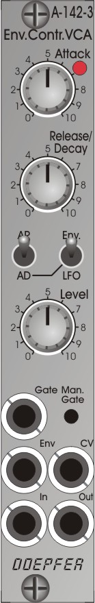
Standard Version |
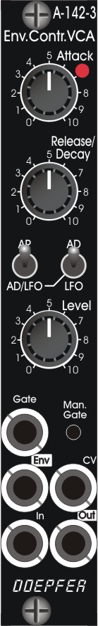
Vintage Edition |
Folgende Bedienelemente und Ein/Ausgänge stehen zur Verfügung:
- LED-Anzeige (zeigt den Hüllkurven- bzw. LFO-Verlauf an)
- Attack: manuelle Einstellung der Attack-Zeit
- Release/Decay: manuelle Einstellung der Release/Decay-Zeit
- Betriebsart-Schalter:
- AD (Attack-Decay Hüllkurve) - AR (Attack-Release-Hüllkurve)
- Envelope oder LFO (LFO nur bei Stellung "AD/LFO" des linken Schalters)
- Level: manuelle Einstellung des Audio-Eingangs-Pegels für den VCAs
- Gate: Gate-Eingang (min. +5V, max. +12V)
- Man. Gate: manueller Gate-Taster
- Env: Envelope/LFO-Ausgang (ca. 0...+10V)
- CV: VCA-Steuer-Eingang, Spannungsbereich ca. 0...+5V, normalisiert auf den Envelope-Ausgang über einen 50% Abschwächer
- In: Audio-Eingang
- Out: Audio-Ausgang
Anwendung:
In nahezu jedem Patch ist eine Kombination aus Hüllkurve und VCA in Verbindung mit einer Klangquelle
sinnvoll, insbesondere für perkussive Klänge.
Technische Informationen:
- Attack und Release/Decay-Zeiten ca. 4 ms ... 7 s oder ca. 0,1ms ... 150 ms, je nach Jumper-Stellung
- Frequenzen im LFO-Modus: ca. 100 Hz ... 0,05 Hz (20 Sekunden Periodendauer) oder ca. 2,5kHz ... 2Hz je nach Jumper-Stellung
-
Mit Hilfe einer internen Steckbrücke (Jumper) kann zwischen 2 Zeit-Bereichen gewählt werden. Bei gesetztem Jumper liegen die Zeit-Bereiche für Attack und Release/Decay bei ca. 4 ms ... 7 s, bei abgezogenem Jumper bei ca. 0,1ms ... 150 ms
-
Mit Hilfe eines Trimmpotentiometers kann der Pegel eingestellt werden, bei dem die fallende in die steigende Flanke im LFO-Modus übergeht. Das beeinflusst auch die Frequenzbereiche im LFO-Modus, da die Länge der fallende Flanke die Frequenz mitbestimmt)
-
Der Spannungspegel des verwendeten Gate-Signals muss mindestens +5V betragen und steile Flanken aufweisen. Andernfalls wird die Hüllkurve nicht korrekt getriggert.
-
Der VCA ist nur für Audio-Signale geeignet (AC-gekoppelt), für die Verarbeitung von Steuerspannungen ist das Modul nicht geeignet.
-
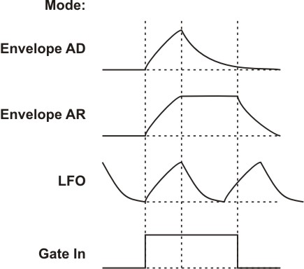
Der Hüllkurven-Generator besitzt exponentielle Kurvenformen (Lade/Entladekurven von Kondensatoren)
-
Im LFO-Modus besitzen die Flanken ebenfalls exponentielle Kurvenformen (siehe Abbildung)
-
Wird dem Modul im LFO-Modus ein Gate-Signal zugeführt, so überlagern sich die die Gate-gesteuerte Hüllkurve und das LFO-Signal
-
Sowohl im Envelope- wir auch im LFO-Modus beträgt die Ausgangsspannung ca. 0...+10V (d.h. auch der LFO ist nicht nullsymmetrisch, sondern erzeugt rein positive Spannungen)
-
Der Envelope-Ausgang wird intern um die Hälfte abgeschwächt (d.h. 0...+10V -> 0...+5V) bevor er auf den CV-Eingang des VCAs normalisiert wird.
-
Der Steuerspannungsbereich des VCAs bei externer Ansteuerung liegt bei ca. 0...+5V.
-
Der VCA hat eine lineare Kennlinie
-
Der manuelle Gate-Taster kann auch dazu verwendet werden, ein extern zugeführte Gate-Signal zu "muten" (d.h. solange der Taster betätigt wird, ist das externe Gate-Signal nicht wirksam).
-
Bei dem Modul handelt es sich nicht um einen halben A-142-2 ! Sowohl die Hüllkurven/LFO- wie auch die VCA-Schaltung sind gegenüber dem A-142-2 völlig anders aufgebaut. Hüllkurve und LFO basieren auf einer Timer-Schaltung (555) und beim VCA kommt der CEM3381 zum Einsatz.
-
Durch Ändern der Steckbrücken können die Werkseinstellungen geändert werden. Das folgende Dokument beschreibt die Funktionen und Positionen der Steckbrücken (Jumper) und Trimmpotentiometer des Moduls:
A142_3_trimming_potentiometers_and_jumpers.pdf
|
Module A-142-3 contains an envelope controlled
VCA
behind a front panel with 4 HP only. It is the combination of a VCA and a AD/AR envelope generator,
that can work also as an LFO. The
envelope generator has exponential curve shapes (charge/discharge curves of a
capacitor). The VCA has a linear control scale.
The module provides these controls and in/outputs:
Applications:
Additional technical information:
|
Breite/Width: 4 TE / 4 HP / 20.0 mm
Tiefe/Depth: 45 mm (gemessen ab der Rückseite der Frontplatte / measured
from the rear side of the front panel)
Strombedarf/Current: +20 mA (+12V) / -20 mA
(-12V)
Standard Version : Euro 100.00
Vintage Edition : Euro 110.00
The price in US$ depends upon the exchange rate between Euro and US$ at the payment day